Panasonic PT52LCX66 Service Manual
Panasonic PT52LCX66 - MULTI MEDIA DISPLAY Manual
 |
View all Panasonic PT52LCX66 manuals
Add to My Manuals
Save this manual to your list of manuals |
Panasonic PT52LCX66 manual content summary:
- Panasonic PT52LCX66 | Service Manual - Page 1
ORDER NO. MKE0605850CE B2 Multi Media Display PT-52LCX66 PT-56LCX66 PT-61LCX66 PT-52LCX16 PT-56LCX16 © 2006 Panasonic Shikoku Electronics Co., Ltd. All rights reserved. Unauthorized copying and distribution is a violation of law. - Panasonic PT52LCX66 | Service Manual - Page 2
Sensitive (ES) Devices 3 Service Navigation 3.1. Introduction 3.2. About Lead Free Solder (PbF) 4 Specifications 5 Location of Controls and Components 5.1. Operation Instructions 5.2. Replacement of Lamp 6 Service Mode 7 Troubleshooting Guide 7.1. Troubleshooting Hints for Block Level Repair - Panasonic PT52LCX66 | Service Manual - Page 3
AC Plug before disassembling this unit. 3. It is advisable to use an isolation transformer in the AC supply before servicing. 4. When servicing, observe the original lead dress. If a short circuit is found, replace all parts which have been overheated or damaged by the short circuit. 5. After - Panasonic PT52LCX66 | Service Manual - Page 4
PT-52LCX66 / PT-56LCX66 / PT-61LCX66 / PT-52LCX16 / PT-56LCX16 2 Warning 2.1. Prevention of Electro Static Discharge (ESD) Be sure no power is applied to the chassis or circuit, and observe all other safety precautions. 8. Minimize bodily motions when handling unpackaged replacement ES devices. ( - Panasonic PT52LCX66 | Service Manual - Page 5
3 Service Navigation PT-52LCX66 / PT-56LCX66 / PT-61LCX66 / PT-52LCX16 / PT-56LCX16 3.1. Introduction This service manual contains technical information which will allow service personnel´s to understand and service this model. Please place orders using the parts list and not the drawing - Panasonic PT52LCX66 | Service Manual - Page 6
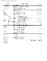
PT-52LCX66 / PT-56LCX66 / PT-61LCX66 / PT-52LCX16 / PT-56LCX16 4 Specifications 6 - Panasonic PT52LCX66 | Service Manual - Page 7
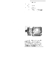
PT-52LCX66 / PT-56LCX66 / PT-61LCX66 / PT-52LCX16 / PT-56LCX16 5 Location of Controls and Components 5.1. Operation Instructions 7 - Panasonic PT52LCX66 | Service Manual - Page 8
PT-52LCX66 / PT-56LCX66 / PT-61LCX66 / PT-52LCX16 / PT-56LCX16 8 - Panasonic PT52LCX66 | Service Manual - Page 9
PT-52LCX66 / PT-56LCX66 / PT-61LCX66 / PT-52LCX16 / PT-56LCX16 9 - Panasonic PT52LCX66 | Service Manual - Page 10
PT-52LCX66 / PT-56LCX66 / PT-61LCX66 / PT-52LCX16 / PT-56LCX16 5.2. Replacement of Lamp 10 - Panasonic PT52LCX66 | Service Manual - Page 11
LEDs on the front flash. PT-52LCX66 / PT-56LCX66 / PT-61LCX66 / PT-52LCX16 / PT-56LCX16 LAMP LED TEMP LED POWER LED (Note 4) (Note 1, 2) (Note 3) Error No. Error Information POWER LED TEMP LED flashes orange flashes red LAMP LED flashes red SOS LAMP OFF RESET 1) SOS2 (Over voltage/current - Panasonic PT52LCX66 | Service Manual - Page 12
PT-52LCX66 / PT-56LCX66 / PT-61LCX66 / PT-52LCX16 / PT-56LCX16 MAIN PARTS LOCATION TEMP LED Power Switch P.C.B. LAMP LED POWER LED TEMP LED LAMP LED Lamp Cover Front Cover Unit Optical Cover SD Card P.C.B. Front Jack /Operation P.C.B. Digital Tuner P.C.B. Main - Panasonic PT52LCX66 | Service Manual - Page 13
PT-52LCX66 / PT-56LCX66 / PT-61LCX66 / PT-52LCX16 / PT-56LCX16 TO DISTINGUISH THE PROJECTION UNIT The only difference between the 52/56 inch model and 61 inch model of the Projection Unit is the LCD Drive P.C.B. Therefore, see the stamp on the Lamp Wall to differentiate. Also, the Focus Adjustment - Panasonic PT52LCX66 | Service Manual - Page 14
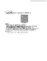
and the OK key on the remote for more than 3 seconds. When reset is finished, power shuts off automatically (the user's memory is reset). CLOGGED AIR FILTER DETECTION When a dirty or clogged air filter is detected, the OSD display appears for 1 minute. And then the Lamp is turned OFF. When this OSD - Panasonic PT52LCX66 | Service Manual - Page 15
the user's location, set the TOTAL value to the original value in Service Mode. 15 Fig. 3 Service Mode Map Enter: VOLUME DOWN button + TV/VIDEO key (on the front) (on the remote) (for more than 5 seconds in power off condition) Power ON SERVICE Mode 1/4 LAMP OPERATION - Panasonic PT52LCX66 | Service Manual - Page 16
PT-52LCX66 / PT-56LCX66 / PT-61LCX66 / PT-52LCX16 / PT-56LCX16 WIRE AND LEAD POSITION DIAGRAM OF THE UNIT After servicing, make sure that all wires, leads, and clampers are placed in their original position. It is important for the best operation of the unit. Note: Use extreme care especially for - Panasonic PT52LCX66 | Service Manual - Page 17
PT-52LCX66 / PT-56LCX66 / PT-61LCX66 / PT-52LCX16 / PT-56LCX16 After servicing, make sure that all wires, leads, and clampers are placed in their original position. It is important for the best operation of the unit. Note: Use extreme care especially for the following. Speaker Connectors CN6001 - Panasonic PT52LCX66 | Service Manual - Page 18
PT-52LCX66 / PT-56LCX66 / PT-61LCX66 / PT-52LCX16 / PT-56LCX16 After servicing, make sure that all wires, leads, and clampers are placed in their original P.C.B.) Clamper CN1520 CN1516 (From (From Base Thermal P.C.B.) Fuse) Power PCB Mount Metal CN9501 (No connection) CN9500 (From Hall-S P.C.B.) - Panasonic PT52LCX66 | Service Manual - Page 19
/ PT-56LCX16 After servicing, make sure that all wires, leads, and clampers are placed in their original position. It is important for the best operation of the unit. Note: Use extreme care especially for the following. Clamper P2821 (Thermistor 2 P.C.B.) Thermal Fuse Speaker Connector Power - Panasonic PT52LCX66 | Service Manual - Page 20
PT-52LCX66 / PT-56LCX66 / PT-61LCX66 / PT-52LCX16 / PT-56LCX16 After servicing, make sure that all wires, leads, and clampers are placed in their original position. It is important for the best operation of the unit. Note: Use extreme care especially for the following. Clampers TV Unit with - Panasonic PT52LCX66 | Service Manual - Page 21
7 Troubleshooting Guide PT-52LCX66 / PT-56LCX66 / PT-61LCX66 / PT-52LCX16 / PT-56LCX16 7.1. Troubleshooting Hints for Block Level Repair MAIN PARTS LOCATION TEMP LED Power Switch P.C.B. LAMP LED POWER LED TEMP LED LAMP LED Lamp Cover Front Cover Unit Optical Cover - Panasonic PT52LCX66 | Service Manual - Page 22
PT-52LCX66 / PT-56LCX66 / PT-61LCX66 / PT-52LCX16 / PT-56LCX16 LED INDICATIONS FOR ERROR CONDITIONS Each LED indication facilitates finding the cause of an error. When an error is detected, the Lamp goes off and the LEDs on the front flash. LAMP LED TEMP LED POWER LED Error No. Error Information - Panasonic PT52LCX66 | Service Manual - Page 23
PT-52LCX66 / PT-56LCX66 / PT-61LCX66 / PT-52LCX16 / PT-56LCX16 Protection Circuit SOS terminal of IC6001 (Main microcontroller) and IC2301 (LCD Microcontroller) IC6001 (MAIN MICROCONTROLLER) (Error No. 11) LAMP SW 1 REG 2 IC1100 DC-DC CONVERTER POWER P.C.B. (Over voltage Detect) DT+9V DT+5V - Panasonic PT52LCX66 | Service Manual - Page 24
PT-52LCX66 / PT-56LCX66 / PT-61LCX66 / PT-52LCX16 / PT-56LCX16 3) Abnormal voltage (DT+5V line) detection circuit TEMPERATURE SENSOR 2 1 MAIN P.C.B. LCD DRIVE P.C.B. THERMISTOR 2 P.C.B. 7) Clogged air filter detection circuit IC2702 +9V 2 DRIVE 4 IC6001 (MAIN MICROCONTROLLER) I2C SERIAL - Panasonic PT52LCX66 | Service Manual - Page 25
PT-52LCX66 / PT-56LCX66 / PT-61LCX66 / PT-52LCX16 / PT-56LCX16 8) Abnormal Lamp detection circuit IC6001 (MAIN MICROCONTROLLER) CN6002 CN1522 CN1401 ON OFF Q6012 Q6011 LAMP ON(H) 18 1 1 LAMP ON(H) 16 16 LAMP STATUS 27 Q6001 Q6000 3 3 Q1602 13 13 POWER CONTROL CIRCUIT 2 SOS Normal - Panasonic PT52LCX66 | Service Manual - Page 26
PT-52LCX66 / PT-56LCX66 / PT-61LCX66 / PT-52LCX16 / PT-56LCX16 AC stop detection circuit FULL-WAVE RECTIFIER POWER FACTOR CORRECTION 2 2 Q1601 DRIVE CN1514 CN6000 IC6002 4 RESET 2 IC6006 2 4 1 STBY+3.3V IC6001 (MAIN MICROCONTROLLER) 89 AC STOP(L) Normal SOS MAIN P.C.B. IC1002, IC1003, - Panasonic PT52LCX66 | Service Manual - Page 27
PT-52LCX66 / PT-56LCX66 / PT-61LCX66 / PT-52LCX16 / PT-56LCX16 How to solve problems indicated by the Error Indication of LED (The symptom of all errors is that Lamp goes off or Lamp does not light up) Note: Before performing the troubleshooting, confirm that all connector cables in the unit are - Panasonic PT52LCX66 | Service Manual - Page 28
PT-52LCX66 / PT-56LCX66 / PT-61LCX66 / PT-52LCX16 / PT-56LCX16 LAMP DOES NOT LIGHT UP Plug in the AC Cord. Turn the power ON. Note: 1. Before doing this troubleshooting, confirm that all connector cables in the unit are connected to the connectors correctly. 2. When doing troubleshooting over - Panasonic PT52LCX66 | Service Manual - Page 29
-52LCX66 / PT-56LCX66 / PT-61LCX66 / PT-52LCX16 / PT-56LCX16 HOW TO DETERMINE WHICH P.C.B. IS DEFECTIVE No picture or abnormal picture ABNORMAL PICTURE: No Picture Color (Black and White picture) Abnormal Picture Color Unsynchronized Picture Dark Picture (Only Video1 OR 2 input is NG.) Replace - Panasonic PT52LCX66 | Service Manual - Page 30
PT-52LCX66 / PT-56LCX66 / PT-61LCX66 / PT-52LCX16 / PT-56LCX16 No sound from built-in both L-CH and R-CH Speakers Check that there is an audio signal to the Audio Out Terminal from all input terminals. OK Replace the TV Unit (Base P.C.B. or Power P.C.B.). (All input are NG.) (Only Audio1 OR 2 - Panasonic PT52LCX66 | Service Manual - Page 31
PT-52LCX66 / PT-56LCX66 / PT-61LCX66 / PT-52LCX16 / PT-56LCX16 Tips for determining defective circuit in the case of picture problem PROJECTION UNIT BASE P.C.B. COMPONENT IN (1,2) VIDEO IN (1,2) S-VIDEO IN (1,2) FRONT JACK /OPERATION P.C.B. CN3901 VIDEO IN 3 S-VIDEO IN 3 CN3102 IC3101 VIDEO SW - Panasonic PT52LCX66 | Service Manual - Page 32
PT-52LCX66 / PT-56LCX66 / PT-61LCX66 / PT-52LCX16 / PT-56LCX16 8 Disassembly and Assembly Instructions 8.1. Cabinet Section DISASSEMBLY METHOD OF CABINET SECTION Cabinet section contains following removal procedures: REMOVAL OF THE TV UNIT AND THE DIGITAL TUNER P.C.B. FROM THE CABINET REMOVAL OF THE - Panasonic PT52LCX66 | Service Manual - Page 33
PT-52LCX66 / PT-56LCX66 / PT-61LCX66 / PT-52LCX16 / PT-56LCX16 REMOVAL OF THE TV UNIT AND THE DIGITAL TUNER P.C.B. FROM THE CABINET 1. Remove the Rear Cover Unit by removing the 13 Screws (401) then pinching the 3 latch tabs. latch tabs 401 Rear Cover Unit Fig. D1-1 33 - Panasonic PT52LCX66 | Service Manual - Page 34
PT-52LCX66 / PT-56LCX66 / PT-61LCX66 / PT-52LCX16 / PT-56LCX16 2. Remove the Connecting Plate R by removing the 2 Screws (401, 402). 3. 1) Remove the 2 Screws (402) on the Connecting Plate F, and remove the Screw (401) on the left side of the TV Unit. 2) Disconnect Connectors CN4501, CN6000, CN6001, - Panasonic PT52LCX66 | Service Manual - Page 35
PT-52LCX66 / PT-56LCX66 / PT-61LCX66 / PT-52LCX16 / PT-56LCX16 Note: Grasping the center of both sides of the sheet or cable with your fingers, slowly and steadily pull the LVDS Cable straight out from the connector. Do not joggle the LVDS cable while disconnecting. Reconnecting is done in the same - Panasonic PT52LCX66 | Service Manual - Page 36
PT-52LCX66 / PT-56LCX66 / PT-61LCX66 / PT-52LCX16 / PT-56LCX16 REMOVAL OF THE PROJECTION UNIT 1. Remove the TV Unit with the Digital Tuner P.C.B. Refer to Steps 1 ~ 2 in "REMOVAL OF THE TV UNIT AND THE DIGITAL TUNER P.C.B. FROM THE CABINET." 2. 1) Remove the 2 Screws (402) on the Connecting Plate F. - Panasonic PT52LCX66 | Service Manual - Page 37
After replacing the Projection Unit, be sure to perform "ADJUSTMENT of Projection Unit." Refer to "WHEN INSTALLING THE PROJECTION UNIT OR THE BASE BODY UNIT INTO THE UNIT AT THE USER'S LOCATION:." 2. These parts will be necessary when replacing. Set aside, keep, and re-use. - Top Duct 3 Unit - Lamp - Panasonic PT52LCX66 | Service Manual - Page 38
PT-52LCX66 / PT-56LCX66 / PT-61LCX66 / PT-52LCX16 / PT-56LCX16 REMOVAL OF THE BASE BODY UNIT 1. Remove the Rear Cover Unit. Refer to Step 1 in "REMOVAL OF THE TV UNIT AND THE DIGITAL TUNER P.C.B. FROM THE CABINET." 2. 1) Remove the Front Cover Unit from the latches. 2) Remove the 5 Screws (454) from - Panasonic PT52LCX66 | Service Manual - Page 39
PT-52LCX66 / PT-56LCX66 / PT-61LCX66 / PT-52LCX16 / PT-56LCX16 REMOVAL OF THE POWER P.C.B. FROM THE CABINET 1. Remove the Rear Cover Unit. Refer to Step 1 in "REMOVAL OF THE TV UNIT AND THE DIGITAL TUNER P.C.B. FROM THE CABINET." 2. 1) Open the Power P.C.B/Power PCB Mount Metal by removing the 6 - Panasonic PT52LCX66 | Service Manual - Page 40
PT-52LCX66 / PT-56LCX66 / PT-61LCX66 / PT-52LCX16 / PT-56LCX16 2) Remove the Power P.C.B. by removing the 5 Screws (479) and release from the spacer. 479 479 479 479 479 Power P.C.B. spacer Power PCB Mount Metal Fig. D4-2 CAUTION: High voltage exists on the Power P.C.B. While removing Power - Panasonic PT52LCX66 | Service Manual - Page 41
PT-52LCX66 / PT-56LCX66 / PT-61LCX66 / PT-52LCX16 / PT-56LCX16 REMOVAL OF THE FRONT JACK/OPERATION P.C.B., THE SD CARD P.C.B., THE MAIN P.C.B., THE BASE P.C.B. FROM THE TV UNIT 1. Remove the TV Unit. Refer to Steps 1 ~ 4 in "REMOVAL OF THE TV 479 402 479 402 402 Connector 752 E60 SD Card P.C.B. - Panasonic PT52LCX66 | Service Manual - Page 42
label Screen Unit PT-56LCX66 PT-56LCX16/-K Fig. D5-1 by TOPPAN LSYK1871 LSYK1872 by KURARAY LSYK1888 LSYK1889 Replacement Note for 56 servicing a 56 inch Screen Unit, remove the Front Cover Unit and confirm the label on the unit. Then, order the correct parts according to the above chart. (PT - Panasonic PT52LCX66 | Service Manual - Page 43
PT-52LCX66 / PT-56LCX66 / PT-61LCX66 / PT-52LCX16 / PT- Replacement Note for 56 inch Screen Unit: Because there are two types of 56 inch Screen Units and individual parts contained in the Screen Unit are not compatible, a label (T or K) is indicated on the Screen Unit. When servicing individual parts - Panasonic PT52LCX66 | Service Manual - Page 44
PT-52LCX66 / PT-56LCX66 / PT-61LCX66 / PT-52LCX16 / PT-56LCX16 REMOVAL OF THE MIRROR FROM THE BACK COVER 1. Remove the Screen Unit. Refer to Steps 1 ~ 2 in "REMOVAL OF THE SCREEN UNIT FROM THE DISPLAY." 2. (For 52 inch models) 1) Remove the 2 Mirror Holder H Units and the 2 Mirror Holder V Units by - Panasonic PT52LCX66 | Service Manual - Page 45
PT-52LCX66 / PT-56LCX66 / PT-61LCX66 / PT-52LCX16 / PT-56LCX16 (For 56/61 inch models) 1) Remove the 3 Mirror Holder H Units and the 2 Mirror Holder V Units by removing the 10 Screws (401). 2) Remove the Mirror from the top by releasing the - Panasonic PT52LCX66 | Service Manual - Page 46
PT-52LCX66 / PT-56LCX66 / PT-61LCX66 / PT-52LCX16 / PT-56LCX16 REMOVAL OF THE POWER SWITCH P.C.B. FROM THE CABINET 1. Remove the Rear Cover Unit. Refer to Step 1 in "REMOVAL OF THE TV UNIT AND THE DIGITAL TUNER P.C.B. FROM THE CABINET." 2. 1) Remove the 2 Screws (465) and disconnect Connector CN6801 - Panasonic PT52LCX66 | Service Manual - Page 47
9 Measurements and Adjustments 9.1. Adjustment Procedures 1 PT-52LCX66 / PT-56LCX66 / PT-61LCX66 / PT-52LCX16 / PT-56LCX16 WHEN INSTALLING THE PROJECTION UNIT OR THE BASE BODY UNIT INTO THE UNIT AT THE USER'S LOCATION: The following ADJUSTMENT of the Projection Unit must be performed. a. Focus - Panasonic PT52LCX66 | Service Manual - Page 48
PT-52LCX66 / PT-56LCX66 / PT-61LCX66 / PT-52LCX16 / PT-56LCX16 a. Focus Adjustment 1) Confirm that each of the pixels in the nine portions are clearly visible. b. Mechanical Picture Position Adjustment (Tilt) 1) Loosen the 4 Screws on the Projection Unit. OPT OPT HPOSI VPOSI F6 02 Screw Screw - Panasonic PT52LCX66 | Service Manual - Page 49
"J", "K", "L" are each almost symmetrical. 6) If not, adjust the "OPT HPOSI" and "OPT VPOSI" (repeat steps 1-6) until the picture is in the correct position. 7) Press the CH UP/DOWN key on the remote to return to the OTHER menu. PT-52LCX66 / PT-56LCX66 / PT-61LCX66 / PT-52LCX16 / PT-56LCX16 49 - Panasonic PT52LCX66 | Service Manual - Page 50
PT-52LCX66 / PT-56LCX66 / PT-61LCX66 / PT-52LCX16 / PT amount of ethyl alcohol) and wipe lightly. Take care not to leave any replaced. Mirror THE FILTER ON THE PROJECTION UNIT CAUTION: Operating with torn or damaged Air Filter LAMP Gently wipe the surface of the glass of the Lamp with cleaning paper or - Panasonic PT52LCX66 | Service Manual - Page 51
(L)/OFF(H)) CN6000 CN6002 POWER SW POWER P.C.B. POWER CONTROL CIRCUIT 2 POWER CONTROL CIRCUIT 1 CN1401 CN1514 CN1522 P2 BALLAST CIRCUIT LAMP POWER SUPPLY AC IN CIRCUIT CN1520 TEMP FUSE SPEAKER-R SPEAKER-L OVERALL BLOCK DIAGRAM PT-52LCX66/PT-56LCX66/PT-61LCX66/PT-52LCX16/PT-56LCX16 51 - Panasonic PT52LCX66 | Service Manual - Page 52
PT-52LCX66 / PT-56LCX66 / PT-61LCX66 / PT-52LCX16 / PT-56LCX16 POWER SUPPLY BLOCK DIAGRAM (1/2) POWER P.C.B. AC IN F1001 6.3A 250V CN1001-1 CN1001-2 L1001 AC LINE FILTER R1005 RUSH CURRENT PROTECTOR RL1902 SUB RELAY L1002 AC LINE FILTER RL1903 MAIN RELAY D1807 IC1404,Q1802 OVER VOLTAGE DET. - Panasonic PT52LCX66 | Service Manual - Page 53
TP2744 TP2739 (7.0V) FAN3 SPEED CONTROL FAN1 LOCK (H) FAN2 LOCK (H) - Panasonic PT52LCX66 | Service Manual - Page 54
INTERFACE) 44 43 48 47 TMDS 52 DECODER 51 40 39 32 I2C SERIAL 10BIT) MODE FREQUENCY (480i)/ 480p 27MHz 720p/ 1080i 74.25MHz AUDIO DATA DECODER MAIN AUDIO (L) 88 1 4.4 dB VCC 8 +9V POWER DOWN(L) VCC 14 +5V 8 +5V TUNER VIDEO PT-52LCX66/PT-56LCX66/PT-61LCX66/PT-52LCX16/PT-56LCX16 54 - Panasonic PT52LCX66 | Service Manual - Page 55
VIDEO SIGNAL PROCESS) PT-52LCX66 / PT-56LCX66 / PT-61LCX66 / PT-52LCX16 / PT-56LCX16 VIDEO SIGNAL IC5011 720p/ 1080i 74.25MHz IP CONVERTER PICTURE CONTROL MULTI WINDOW PICTURE IN PICTURE SPLIT SCREEN SEARCH SCALER(720p 22-25,27,28 CONVERTER 41 42 37 52 38 51 39 40 31 PLL VCC 9,26 - Panasonic PT52LCX66 | Service Manual - Page 56
DAC LATCH 3 4 5 6 7 64 SCALE CONTROL 65 D/A COVERTER SERIAL I/F IC2008 (LEVEL SHIFTER) +15.5V +3.3V 48 RESET(L) 10 PLL 40 41 42 43 44 5 6 8 13,22,34 VDD 12,37,39 VDD LEVEL SHIFTER ON/OFF SW LCD(B) VIDEO SIGNAL PATH II BLOCK DIAGRAM PT-52LCX66/PT-56LCX66/PT-61LCX66/PT-52LCX16/PT-56LCX16 - Panasonic PT52LCX66 | Service Manual - Page 57
CN3102-10 PT-52LCX66 / PT-56LCX66 / PT-61LCX66 / PT-52LCX16 / PT-56LCX16 IC4002 (AUDIO SW) 15 13 19 40 10 8 4 2 17 38 HDMI 1(A) HDMI 2(A) TV LINE 3 LINE MIX 32 CROSS OVER VOLUME CONTROL /LIMITER DDX PROCESSING QUAD HALFBRIDGE POWER AMP 16 10 11 27 12.288MHz CLOCK 2 CN4502-2 CN4502-1 - Panasonic PT52LCX66 | Service Manual - Page 58
MAIN P.C.B. USER ADJUSTMENT DATA ADJUSTMENT DATA STBY+3.3V STBY +3.3V D6802 TEMP Q6802 D6801 POWER D6803 LAMP GREEN Q6803 RED D6805 IRIS LAMP MODE Q6804 Q6805 SW6801 POWER CN6801-3 CN6801-2 CN6801-6 CN6801-5 CN6801-1 CN6001-4 CN6001-3 CN6001-7 CN6001-6 CN6001-2 TO POWER SUPPLY LAMP ON - Panasonic PT52LCX66 | Service Manual - Page 59
GREEN LIGHT IN POLARIZER GREEN UNIT TRIMMING FILTER GREEN CONDENSER LENS INTEGRATOR 2 IRIS MECHANISM UNIT UV/IR FILTER FULL MIRROR BLUE RELAY LENS 1 DICHROIC MIRROR GREEN DICHROIC MIRROR RED P/S CONVERTER INTEGRATOR 1 LAMP PT-52LCX66 / PT-56LCX66 / PT-61LCX66 / PT-52LCX16 / PT-56LCX16 - Panasonic PT52LCX66 | Service Manual - Page 60
PT-52LCX66 / PT-56LCX66 / PT-61LCX66 / PT-52LCX16 / PT-56LCX16 60 - Panasonic PT52LCX66 | Service Manual - Page 61
supplied as a replacement parts. POWER SUPPLY P.C.B. The Number of pins of the Connector. MAIN P.C.B. P1503 244 (10 Pins) P3004 Connector No. on Main P.C.B. SCHEMATIC DIAGRAM AND CIRCUIT BOARD LAYOUT NOTES PT-52LCX66/PT-56LCX66/PT-61LCX66/PT-52LCX16/PT-56LCX16 61 PT-52LCX66 / PT-56LCX66 / PT - Panasonic PT52LCX66 | Service Manual - Page 62
GISINNNOITNSGUPOPFLISECDHAESMAARTEICPLSAECCETMIEONNT.PART. WHEN REPLACING, REPLACE THE LAMP UNIT WHICH IS SUPPLIED AS A OPTIONAL ACCESSORY. NOTE: PARTS MARKED "PT" ARE NOT USED. COMPARISON CHART OF MODELS & MARKS MODEL MARK PT-52LCX66 A PT-56LCX66 B PT-61LCX66 C PT-52LCX16 D PT-56LCX16 - Panasonic PT52LCX66 | Service Manual - Page 63
CH DOWN SW6707 EVQ11G05R CH UP SW6708 EVQ11G05R TV/VIDEO CN3901 TO BASE P.C.B. CN3102 1 L3_CPS_NOSIG_L PT-52LCX66 / PT-56LCX66 / PT-61LCX66 / PT-52LCX16 / PT-56LCX16 NOTE: For placing a purchase order of the parts, be sure to use the part number listed in the parts list. Do not use the part - Panasonic PT52LCX66 | Service Manual - Page 64
BY THE SIGN HAVE SPECIAL CHARACTERISTICS IMPORTANT FOR SAFETY. WHEN REPLACING ANY OF THESE COMPONENTS, USE ONLY THE SPECIFIED PARTS. LSJB3137 POWER SWITCH SCHEMATIC DIAGRAM PT 330 R6815 R6812 470 R6811 470 LAMP TEMP D6805 B3AEA0000066 D6802 B3AAA0000538 D6803 B3AAA0000538 R6802 10k Q6803 - Panasonic PT52LCX66 | Service Manual - Page 65
12.5. VOLTAGE CHART PT-52LCX66 / PT-56LCX66 / PT-61LCX66 / PT-52LCX16 / PT-56LCX16 POWER SWITCH P.C.B. PIN NO. VOLTAGE Q6802 E 3.4 C 3.2 B 2.6 Q6803 E 3.4 C -1.5 B 3.4 Q6804 E0 C 3.3 B0 Q6805 E0 C 3.3 B0 PIN NO. VOLTAGE CN6801 1 --- 2 3.3 3 0.3 4 3.4 5 0 6 0 7 0.1 8 0 PIN NO. - Panasonic PT52LCX66 | Service Manual - Page 66
PT-52LCX66 / PT-56LCX66 / PT-61LCX66 / PT-52LCX16 / PT-56LCX16 66 - Panasonic PT52LCX66 | Service Manual - Page 67
) SW6708 TV/VIDEO R6702 REPLACING ANY OF THESE COMPONENTS, USE ONLY THE SPECIFIED PARTS. R2821 1 2 P2821 LSJB3137 FRONT JACK / OPERATION P.C.B. LSEP3200A POWER SWITCH P.C.B. LSEP3201A THERMISTOR 2 P.C.B. LSEP3137B COVER SWITCH P.C.B. LSEP3160A PT-52LCX66/PT-56LCX66/PT-61LCX66/PT-52LCX16/PT - Panasonic PT52LCX66 | Service Manual - Page 68
PT-52LCX66 / PT-56LCX66 / PT-61LCX66 / PT-52LCX16 / PT-56LCX16 68 - Panasonic PT52LCX66 | Service Manual - Page 69
14 Exploded Views 14.1. MAIN PARTS SECTION PT-52LCX66 / PT-56LCX66 / PT-61LCX66 / PT-52LCX16 / PT-56LCX16 69 - Panasonic PT52LCX66 | Service Manual - Page 70
PT-52LCX66 / PT-56LCX66 / PT-61LCX66 / PT-52LCX16 / PT-56LCX16 70 - Panasonic PT52LCX66 | Service Manual - Page 71
14.2. BASE BODY SECTION PT-52LCX66 / PT-56LCX66 / PT-61LCX66 / PT-52LCX16 / PT-56LCX16 71 - Panasonic PT52LCX66 | Service Manual - Page 72
PT-52LCX66 / PT-56LCX66 / PT-61LCX66 / PT-52LCX16 / PT-56LCX16 14.3. DISPLAY SECTION 72 - Panasonic PT52LCX66 | Service Manual - Page 73
PT-52LCX66 / PT-56LCX66 / PT-61LCX66 / PT-52LCX16 / PT-56LCX16 73 - Panasonic PT52LCX66 | Service Manual - Page 74
PT-52LCX66 / PT-56LCX66 / PT-61LCX66 / PT-52LCX16 / PT-56LCX16 14.4. SCREEN SECTION 74 - Panasonic PT52LCX66 | Service Manual - Page 75
PT-52LCX66 / PT-56LCX66 / PT-61LCX66 / PT-52LCX16 / PT-56LCX16 75 - Panasonic PT52LCX66 | Service Manual - Page 76
PT-52LCX66 / PT-56LCX66 / PT-61LCX66 / PT-52LCX16 / PT-56LCX16 14.5. PROJECTION SECTION 76 - Panasonic PT52LCX66 | Service Manual - Page 77
14.6. TV UNIT SECTION PT-52LCX66 / PT-56LCX66 / PT-61LCX66 / PT-52LCX16 / PT-56LCX16 77 - Panasonic PT52LCX66 | Service Manual - Page 78
PT-52LCX66 / PT-56LCX66 / PT-61LCX66 / PT-52LCX16 / PT-56LCX16 14.7. PACKING PARTS AND ACCESSORIES SECTION 78 - Panasonic PT52LCX66 | Service Manual - Page 79
15 Replacement Parts List PT-52LCX66 / PT-56LCX66 / PT-61LCX66 / PT-52LCX16 / PT-56LCX16 BEFORE REPLACING PARTS, READ THE FOLLOWING: 15.1.3. Electrical Replacement Notes 15.1. REPLACEMENT NOTES 15.1.1. General Notes 1. Use only original replacement parts: To maintain original function and - Panasonic PT52LCX66 | Service Manual - Page 80
PT-52LCX66 / PT-56LCX66 / PT-61LCX66 / PT-52LCX16 / PT-56LCX16 15.2. MECHANICAL REPLACEMENT PARTS LIST Definition of Parts supplier: 1. Parts with mark "PSEC" in the Remarks column are supplied from PSEC. 2. Parts without mark in the Remarks column are supplied from PASC-NPC. Ref. No. 1 3 5 6 7 8 - Panasonic PT52LCX66 | Service Manual - Page 81
6 CONNECTOR CABLE W/PLUG 5 PSEC MAIN P.C.B. ( A,B,C ) 6 RTL MAIN P.C.B. ( D,E ) 6 RTL BASE P.C.B. ( A,B,C ) 6 RTL BASE P.C.B. ( D,E ) 6 RTL POWER P.C.B. 5 RTL PSEC Ref. No. E40 E50 E60 E100 E130 E140 E150 24 492 PT-52LCX66 / PT-56LCX66 / PT-61LCX66 / PT-52LCX16 / PT-56LCX16 Part No - Panasonic PT52LCX66 | Service Manual - Page 82
PT-52LCX66 / PT-56LCX66 / PT-61LCX66 / PT-52LCX16 / PT-56LCX16 Ref. No. E130 Part No. LSEP3137B Part Name & Description THERMISTOR 2 P.C.B. E140 LSEP3160A COVER SWITCH P.C.B. E150 LSXA0773 IRIS P.C.B. Remarks RTL PSEC RTL PSEC RTL PSEC 15.4.1. POWER SWITCH P.C.B. Ref. No. Q6802 or Q6802 or - Panasonic PT52LCX66 | Service Manual - Page 83
15.4.5. ELECTRICAL PARTS LOCATED ON CHASSIS Ref. No. F001 FUSE & PROTECTOR Part No. Part Name & Description LSJA0583 THERMAL FUSE UNIT Remarks PSEC PT-52LCX66 / PT-56LCX66 / PT-61LCX66 / PT-52LCX16 / PT-56LCX16 83
-
 1
1 -
 2
2 -
 3
3 -
 4
4 -
 5
5 -
 6
6 -
 7
7 -
8
-
9
-
10
-
11
-
12
-
13
-
14
-
15
-
16
-
17
-
18
-
19
-
20
-
21
-
22
-
23
-
24
-
25
-
26
-
27
-
28
-
29
-
30
-
31
-
32
-
33
-
34
-
35
-
36
-
37
-
38
-
39
-
40
-
41
-
42
-
43
-
44
-
45
-
46
-
47
-
48
-
49
-
50
-
51
-
52
-
53
-
54
-
55
-
56
-
57
-
58
-
59
-
60
-
61
-
62
-
63
-
64
-
65
-
66
-
67
-
68
-
69
-
70
-
71
-
72
-
73
-
74
-
75
-
76
-
77
-
78
-
79
-
80
-
81
-
82
-
83
 |
 |
©
2006 Panasonic Shikoku Electronics Co., Ltd. All
rights
reserved.
Unauthorized
copying
and
distribution is a violation of law.
PT-52LCX66
PT-56LCX66
PT-61LCX66
PT-52LCX16
PT-56LCX16
Multi Media Display
ORDER NO. MKE0605850CE
B2