Panasonic PT56LCZ7 Lifi Hdtv - Page 19
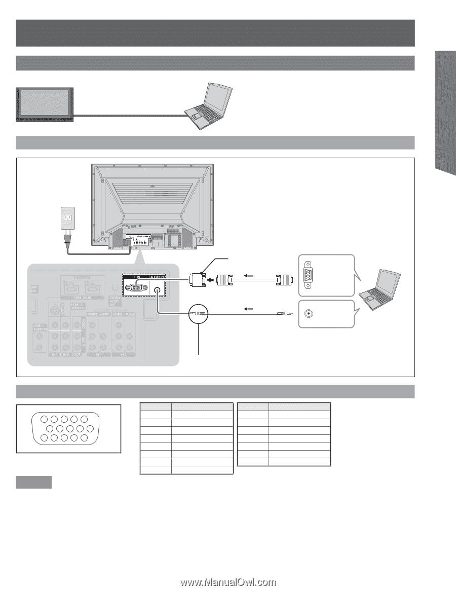
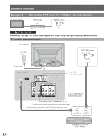
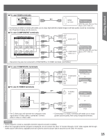
Example 5, Connecting PC, To connect PC terminals, PC IN Terminal D-SUB 15P Pin Layouts
 |
View all Panasonic PT56LCZ7 manuals
Add to My Manuals
Save this manual to your list of manuals |
Page 19 highlights
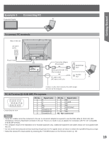
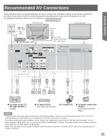
Getting Started Example 5 Connecting PC Projection Display PC To connect PC terminals Back of the unit AC 120 V 60 Hz Power Cord Conversion adapter (If necessary) RGB cable (D-SUB 15P) (Not included) PC audio cable (M3 stereo mini pin) MONITOR OUT AUDIO OUT PC Connect a cable which matches the audio output terminal on the computer. PC IN Terminal (D-SUB 15P) Pin Layouts 54321 10 9 8 7 6 15 14 13 12 11 Connection port view Pin No. 1 2 3 4 5 6 7 8 Signal name R G B NC NC Ground for R Ground for G Ground for B Pin No. Signal name 9 NC 10 Ground 11 NC 12 NC 13 HD/CSYNC 14 VD 15 NC NC: Not connected Notes • Some PC models cannot be connected to the set. A conversion adapter is required to use the RGB cable (D-SUB 15P) (Not included) to connect a Macintosh computer to the set. There is no need to use an adapter for computers with PC / AT compatible D-SUB 15P terminal. • The computer shown in the illustration is for example purposes only. Additional equipment and cables shown are not supplied with this set. • Do not set the horizontal and vertical scanning frequencies for PC signals which are above or below the specified frequency range. • Select the desired PC input position by pressing the TV/VIDEO button on the Remote Control. (p. 29) 19
-
 1
1 -
2
-
3
-
4
-
5
-
6
-
7
-
8
-
9
-
10
-
11
-
12
-
13
-
 14
14 -
 15
15 -
 16
16 -
 17
17 -
 18
18 -
 19
19 -
 20
20 -
 21
21 -
 22
22 -
 23
23 -
 24
24 -
25
-
26
-
27
-
28
-
29
-
30
-
31
-
32
-
33
-
34
-
35
-
36
-
37
-
38
-
39
-
40
-
41
-
42
-
43
-
44
-
45
-
46
-
47
-
48
-
49
-
50
-
51
-
52
-
53
-
54
-
55
-
56
-
57
-
58
-
59
-
60
-
61
-
62
-
63
-
64
-
65
-
66
-
67
-
68
 |
 |