Panasonic PT56LCZ7 Lifi Hdtv - Page 29

Projection Display Operation

Page 29 highlights

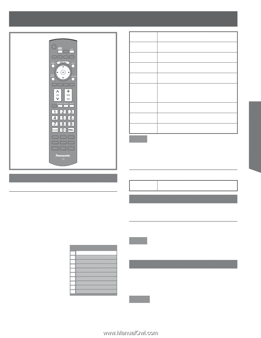
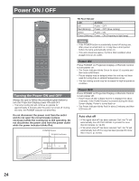
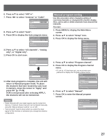
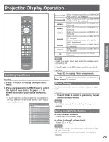
Projection Display Operation Basic Operation Selecting Input Mode Procedure 1. Press TV/VIDEO to display the Input select menu. 2. Press corresponding NUMBER keys to select the input of your choice. Or, press ▲▼ to select the input of your choice, then press OK. • If, during selection, no action is taken for several seconds, the Input selection menu is exited and the current input is automatically selected. Input select 1 TV 2 Component 1 3 Component 2 4 HDMI 1 5 HDMI 2 6 HDMI 3 7 Video 1 8 Video 2 9 Video 3 0 PC Component 1 Component 2 HDMI 1 HDMI 2 HDMI 3 Video 1 Video 2 Video 3 PC Signal of source connected to COMPONENT VIDEO INPUT 1 is displayed. Signal of source connected to COMPONENT VIDEO INPUT 2 is displayed. Signal of source connected to HDMI IN 1 is displayed. Signal of source connected to HDMI IN 2 is displayed. Signal of source connected to HDMI IN 3 is displayed. Signal of source connected to VIDEO INPUT 1 is displayed. Signal of source connected to S VIDEO INPUT is displayed. Signal of source connected to VIDEO INPUT 2 is displayed. Signal of source connected to VIDEO INPUT 3 is displayed. Signal of source connected to PC IN is displayed. Note • If SKIP is set as the Input Label setting, the mode will not be changed. (p. 50) ■ Card input mode (Photo viewer) is selected. Procedure 1. Press SD to display Photo viewer mode. Photo Signal of source connected to CARD SLOT (Photo viewer) is displayed. Rapid Tuning Switches between the current and last channel or input modes. Procedure 1. Press R-TUNE to switch to previously viewed channel or input modes. Note • When Photo viewer (p. 46) is used, Rapid Tuning is not available. Using the CH/VOL Button ■ Select desired channel: Press CH or NUMBER keys. ■ Adjust to desired volume level: Press VOL+ or VOL-. Notes • The channel number and volume level are stored even after the unit is turned off. • Power consumption can be reduced if the volume level is lowered. 29

  • 1
  • 2
  • 3
  • 4
  • 5
  • 6
  • 7
  • 8
  • 9
  • 10
  • 11
  • 12
  • 13
  • 14
  • 15
  • 16
  • 17
  • 18
  • 19
  • 20
  • 21
  • 22
  • 23
  • 24
  • 25
  • 26
  • 27
  • 28
  • 29
  • 30
  • 31
  • 32
  • 33
  • 34
  • 35
  • 36
  • 37
  • 38
  • 39
  • 40
  • 41
  • 42
  • 43
  • 44
  • 45
  • 46
  • 47
  • 48
  • 49
  • 50
  • 51
  • 52
  • 53
  • 54
  • 55
  • 56
  • 57
  • 58
  • 59
  • 60
  • 61
  • 62
  • 63
  • 64
  • 65
  • 66
  • 67
  • 68

29
Basic Operation
Selecting Input Mode
Procedure
1. Press TV/VIDEO to display the Input select
menu.
2. Press corresponding NUMBER keys to select
the input of your choice. Or, press
▲▼
to
select the input of your choice, then press
OK.
If, during selection, no action is taken for several seconds,
the Input selection menu is exited and the current input is
automatically selected.
TV
Component 1
Component 2
HDMI 1
HDMI 2
HDMI 3
Video 1
Video 2
Video 3
PC
1
2
3
4
5
6
7
8
9
0
Input select
Note
If SKIP is set as the Input Label setting, the mode will not be
changed. (p. 50)
Card input mode (Photo viewer) is selected.
Procedure
1. Press SD to display Photo viewer mode.
Rapid Tuning
Switches between the current and last channel or input
modes.
Procedure
1. Press R-TUNE to switch to previously viewed
channel or input modes.
Note
When Photo viewer (p. 46) is used, Rapid Tuning is not
available.
Using the
CH/VOL Button
Select desired channel:
Press CH
<
>
or NUMBER keys.
Adjust to desired volume level:
Press VOL+ or VOL-.
Notes
The channel number and volume level are stored even after
the unit is turned off.
Power consumption can be reduced if the volume level is
lowered.
Component 1
Signal of source connected to COMPONENT
VIDEO INPUT 1 is displayed.
Component 2
Signal of source connected to COMPONENT
VIDEO INPUT 2 is displayed.
HDMI 1
Signal of source connected to HDMI IN 1 is
displayed.
HDMI 2
Signal of source connected to HDMI IN 2 is
displayed.
HDMI 3
Signal of source connected to HDMI IN 3 is
displayed.
Video 1
Signal of source connected to VIDEO INPUT
1 is displayed.
Signal of source connected to S VIDEO
INPUT is displayed.
Video 2
Signal of source connected to VIDEO INPUT
2 is displayed.
Video 3
Signal of source connected to VIDEO INPUT
3 is displayed.
PC
Signal of source connected to PC IN is
displayed.
Photo
(Photo viewer)
Signal of source connected to CARD SLOT
is displayed.
Photo
(Photo viewer)
Signal of source connected to CARD SLOT
is displayed.
Projection Display Operation