Panasonic SAHT640 SAHT640 User Guide - Page 5
STEP 2 SPEAKER CONNECTIONS, Speaker installation options
 |
View all Panasonic SAHT640 manuals
Add to My Manuals
Save this manual to your list of manuals |
Page 5 highlights
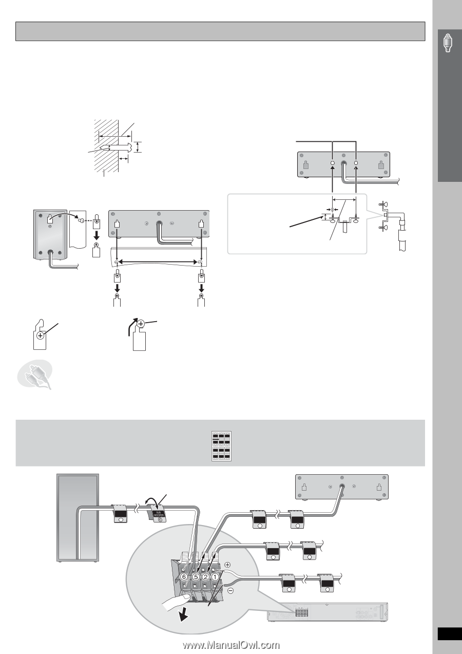
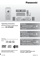
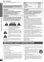
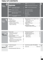
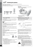
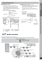
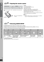
Simple Setup Speaker installation options ∫ Attaching to a wall You can attach the front and center speakers to a wall. ≥ The wall or pillar on which the speakers are to be attached should be capable of supporting 10 kg (22 lbs) per screw. Consult a qualified building contractor when attaching the speakers to a wall. Improper attachment may result in damage to the wall and speakers. 1 Drive a screw (not included) into the wall. 30 to 35 mm (13/16q to 13/8q) ‰3.0 to 4.0 mm (1/8q to 5/32q) Wall or pillar ‰7.5 to 9.4 mm (19/64q to 3/8q) 4.0 to 7.0 mm (5/32q to 9/32q) 2 Fit the speaker securely onto the screw(s) with the hole(s). Front speaker Center speaker ∫ Fitting speaker stands (not included) Ensure the stands meet these conditions before purchasing them. Note the diameter and length of the screws and the distance between screws as shown in the diagram. ≥ The stands must be able to support over 10 kg (22 lbs). ≥ The stands must be stable even if the speakers are in a high position. e.g. Center speaker Metal screw holes For attaching to speaker stands 5 mm (3/16q), pitch 0.8 mm (1/32q) 200 mm (77/8z) Plate thickness plus 7 mm to 10 mm (plus 9/32q to 13/32q) 60 mm (23/8q) Speaker stand (not included) Positioning the speakers / Speaker connections e.g. In this position, the speaker will likely fall if moved to the left or right. Move the speaker so that the screw is in this position. 2 STEP Speaker connections ≥ Attach the speaker-cable stickers to make connection easier. ≥ Be careful not to cross (short-circuit) or reverse the polarity of the speaker wires as doing so may damage the speakers. 2 sheets of speaker cable stickers CENTER 5 SURROUND Lch 3 FRONT Lch 1 ≥ The stickers for the surround FRONT Lch 1 SURROUND Lch 3 CENTER 5 speakers are not to be used. SUB WOOFER 6 SURROUND Rch 4 FRONT Rch 2 FRONT Rch 2 SURROUND Rch 4 SUB WOOFER 6 Speaker cable sticker 5 CENTER SUB WOOFER 6 CENTER 5 CENTER 5 FRONT Rch 2 2 FRONT (R) FRONT Rch 2 6 SUBWOOFER FRONT Lch 1 1 FRONT (L) FRONT Lch 1 Main unit RQT8611 Push! Insert the wire fully. i: White j: Blue DIGITAL TRANSCEIVER 5
-
 1
1 -
 2
2 -
 3
3 -
 4
4 -
 5
5 -
 6
6 -
 7
7 -
 8
8 -
 9
9 -
 10
10 -
 11
11 -
12
-
13
-
14
-
15
-
16
-
17
-
18
-
19
-
20
-
21
-
22
-
23
-
24
-
25
-
26
-
27
-
28
-
29
-
30
-
31
-
32
-
33
-
34
-
35
-
36
 |
 |