Panasonic SAHT640 SAHT640 User Guide - Page 6
STEP 3 AUDIO AND VIDEO CONNECTIONS, Basic audio connection
 |
View all Panasonic SAHT640 manuals
Add to My Manuals
Save this manual to your list of manuals |
Page 6 highlights
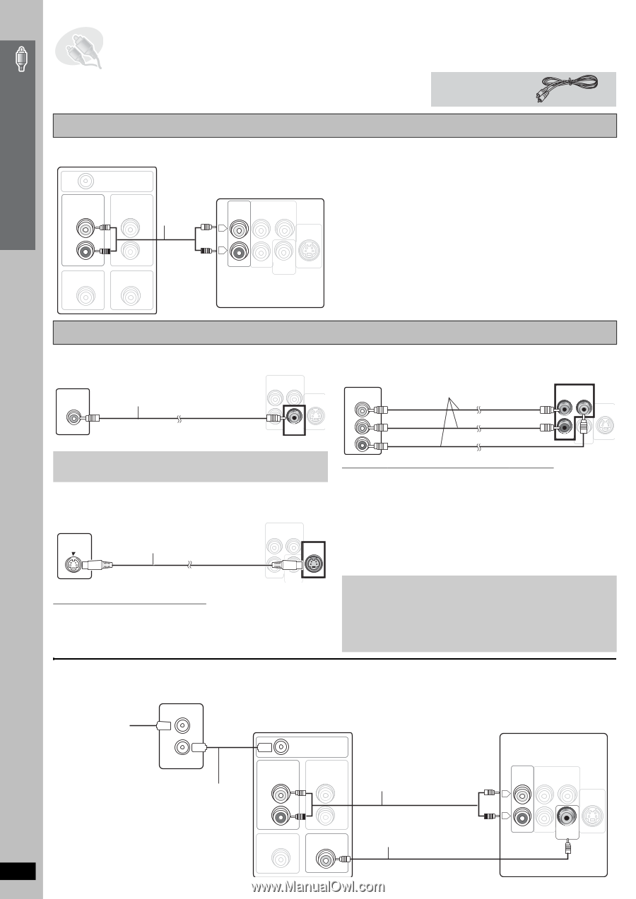
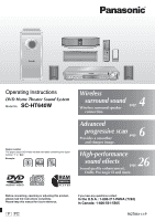
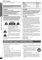
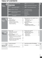
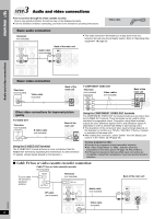
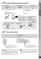
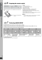
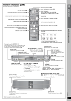
Simple Setup 3 STEP Audio and video connections ≥ Do not connect through the video cassette recorder. Due to copy guard protection, the picture may not be displayed properly. ≥ Turn the television off before connecting, and refer to the television's operating instructions. Video cable Basic audio connection Television (not included) RF IN AUDIO OUT L AUDIO IN R VIDEO OUT VIDEO IN Back of the main unit Audio cable (not included) L AUX COMPONENTVIDEOOUT PB Y S-VIDEO OUT R PR VIDEO OUT ≥ This audio connection will enable you to play audio from your television through your home theater system. Refer to "Operating other equipment" (➜ page 28). Audio and video connections Basic video connection Television (not included) VIDEO IN Video cable (included) Back of the main unit COMPONENT VIDEO OUT PB Y S-VIDEO OUT PR VIDEO OUT Other video connections for improved picture quality ≥ S-VIDEO OUT Television (not included) S-VIDEO IN S-video cable (not included) Back of the main unit COMPONENT VIDEO OUT PB Y S-VIDEO OUT PR VIDEO OUT Using the S-VIDEO OUT terminal The S-VIDEO OUT terminal achieves a more vivid picture than the VIDEO OUT terminal by separating the chrominance (C) and luminance (Y) signals. (Actual results depend on the television.) ≥ COMPONENT VIDEO OUT Television (not included) COMPONENT VIDEO IN Video cables (not included) PB Back of the main unit COMPONENT VIDEO OUT PB Y S-VIDEO OUT PR PR VIDEO OUT Y Using the COMPONENT VIDEO OUT terminals The COMPONENT VIDEO OUT terminals provides a purer picture than the S-VIDEO OUT terminal. These terminals can be used for either interlaced or progressive output. Connection using these terminals outputs the color difference signals (PB/PR) and luminance signal (Y) separately in order to achieve high fidelity in reproducing colors. ≥ The description of the component video input terminals depends on the television or monitor (e.g. Y/PB/PR, Y/B-Y/R-Y, Y/CB/CR). Connect to terminals of the same color. ≥ After making this connection, select "Darker" from the "Black Level Control" in the "Video" tab (➜ page 22). To enjoy progressive video ≥ Connect to a progressive output compatible television. ≥ Set "Video Output Mode" to "480p", and then follow the instructions on the menu screen (➜ page 19, Picture Menu). ≥ All Panasonic televisions that have 480p input connectors are compatible. Consult the manufacturer if you have another brand of television. ∫ Cable TV box or video cassette recorder connection Cable TV box or video cassette recorder (not included) To your cable TV service or television antenna RF IN RF OUT RF cable (not included) Television (not included) RF IN AUDIO OUT L AUDIO IN Audio cable (not included) R VIDEO OUT VIDEO IN Video cable (included) Back of the main unit AUX COMPONENTVIDEOOUT PB Y L S-VIDEO OUT R PR VIDEO OUT RQT8611 6
-
 1
1 -
 2
2 -
 3
3 -
 4
4 -
 5
5 -
 6
6 -
 7
7 -
 8
8 -
 9
9 -
 10
10 -
 11
11 -
 12
12 -
13
-
14
-
15
-
16
-
17
-
18
-
19
-
20
-
21
-
22
-
23
-
24
-
25
-
26
-
27
-
28
-
29
-
30
-
31
-
32
-
33
-
34
-
35
-
36
 |
 |