Panasonic WU-216MF1U9E Service Manual
Panasonic WU-216MF1U9E Manual
 |
View all Panasonic WU-216MF1U9E manuals
Add to My Manuals
Save this manual to your list of manuals |
Panasonic WU-216MF1U9E manual content summary:
- Panasonic WU-216MF1U9E | Service Manual - Page 1
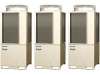
TEST RUN SERVICE MANUAL U-72MF1U9 U-72MF1U9E* U-96MF1U9 U-96MF1U9E* TENTATIVE 3WAY VRF SYSTEM 1 2 Model No. Outdoor Units Class 72 96 Model Name U-72MF1U9 U-96MF1U9 U-72MF1U9E* U-96MF1U9E* Refrigerant R410A is used - Panasonic WU-216MF1U9E | Service Manual - Page 2
are all you need for most installation sites and maintenance conditions. If you require help for a special problem, contact our sales/service outlet or your certified dealer for additional instructions. In Case of Improper Installation The manufacturer shall in no way be responsible for improper - Panasonic WU-216MF1U9E | Service Manual - Page 3
Check of Density Limit The room in which the air conditioner is to be installed requires a design that in the event of refrigerant gas leaking out, its density will not exceed a set limit. The refrigerant (R410A), which is used in the airconditioner, is safe, without the toxicity or combustibility - Panasonic WU-216MF1U9E | Service Manual - Page 4
Remote Controller 2-4 3. Timer Remote Controller 2-15 Section 3: TROUBLE DIAGNOSIS 3-1 1. Contents of Remote Controller Switch Alarm Display 3-2 FUNCTION TABLE 5-1 1. Self-Diagnosis Function Table 5-2 Section 6: SERVICE CHECKER 6-1 1. Outdoor Unit Maintenance Remote Controller 6-2 iii - Panasonic WU-216MF1U9E | Service Manual - Page 5
Contents TENTATIVE Test Run 1. TEST RUN 1. Test Run ...1-2 1-1. Preparing for Test Run 1-2 1-2. Test Run Procedure...1-3 2. Setting of Unit Control PCB 1-4 2-1. Main Outdoor Unit PCB Setting 1-4 3. Auto Address Setting ...1-6 3-1. Auto Address Setting...1-6 4. Remote Controller Test Run - Panasonic WU-216MF1U9E | Service Manual - Page 6
to the touch. Power mains switch (6) Both the gas and liquid tube service valves are open. If not, open them now. (7) Request that the customer be present for the trial run. Explain the contents of the instruction manual, then have 1 the customer actually operate the system. (8) Be sure to - Panasonic WU-216MF1U9E | Service Manual - Page 7
2. After performing the leak inspection, applying vacuum, and performing refrigerant charge for the tubing which is connected onsite, fully open the outdoor unit service valve. However if only one outdoor unit is installed, a balance tube is not used. Therefore, leave the valve fully closed. 3. When - Panasonic WU-216MF1U9E | Service Manual - Page 8
2. Setting of Unit Control PCB 2-1. Main Outdoor Unit PCB Setting Test Run 1 2 3 4 CN003 CN101 5 CN100 6 S007 S006 S005 S004 S002 S003 7 1 - 4 - Panasonic WU-216MF1U9E | Service Manual - Page 9
2. Setting of Unit Control PCB Test Run z Examples of the No. of indoor units settings (S005, S004) No. of indoor units 1 unit (factory setting) 11 units 21 units 31 units 40 units Indoor unit setting (S005) (3P DIP switch, blue) 10 20 30 ON ON All OFF 123 OFF ON ON 1 ON 123 OFF ON - Panasonic WU-216MF1U9E | Service Manual - Page 10
3. Auto Address Setting Test Run 3-1. Auto Address Setting Basic wiring diagram: Example (1) • If link wiring is not used (The inter-unit control wires are not connected to multiple refrigerant systems.) Indoor unit addresses can be set without operating the compressors. No. 1 (main outdoor unit - Panasonic WU-216MF1U9E | Service Manual - Page 11
Indoor unit 2-1 Remote controller 2-2 Remote controller cross-over wiring 2-9 5 Make settings as appropriate for the cases listed below. (Refer to the instructions on the following pages.) · Indoor and outdoor unit power can be turned ON for each system separately. · Indoor and outdoor unit - Panasonic WU-216MF1U9E | Service Manual - Page 12
3. Auto Address Setting Test Run Case 2 Automatic Address Setting (no compressor operation) z Indoor and outdoor unit power can be turned ON for each system separately. Indoor unit addresses can be set without operating the compressors. Automatic Address Setting from Outdoor Unit ON 1. On the - Panasonic WU-216MF1U9E | Service Manual - Page 13
3. Auto Address Setting Test Run Case 3A Automatic Address Setting in Heating Mode z Indoor and outdoor unit power cannot be turned ON for each system separately. In the following, automatic setting of indoor unit addresses is not possible if the compressors are not operating. Therefore perform - Panasonic WU-216MF1U9E | Service Manual - Page 14
3. Auto Address Setting Test Run Case 3B Automatic Address Setting in Cooling Mode z Indoor and outdoor unit power cannot be turned ON for each system separately. In the following, automatic setting of indoor unit addresses is not possible if the compressors are not operating. Therefore perform - Panasonic WU-216MF1U9E | Service Manual - Page 15
OFF. * LED 1 is D72. LED 2 is D75. * If automatic address setting is not completed successfully, refer to the table below and correct the problem. Then perform automatic address setting again. z Display of LED 1 and 2 on the outdoor unit control PCB ( : ON : Blinking :OFF) LED1 LED2 Display - Panasonic WU-216MF1U9E | Service Manual - Page 16
operation is not possible, a code is displayed on the remote controller LCD display. (Refer to "Table of Self-Diagnostic Functions" and correct the problem.) 6 4. After the test run is completed, press the button again. Check that "TEST RUN" disappears from the LCD display. (To prevent continuous - Panasonic WU-216MF1U9E | Service Manual - Page 17
means refrigerant gas in the system is returned to the outdoor unit. Pump down is used when the unit is to be moved, or before servicing the refrigerant circuit. CAUTION This outdoor unit cannot collect more than the rated refrigerant amount as shown by the nameplate on the back. If the - Panasonic WU-216MF1U9E | Service Manual - Page 18
6. Meaning of Alarm Messages Test Run 6. Meaning of Alarm Messages Table of Self-Diagnostics Functions and Description of Alarm Displays Alarm messages are indicated by the blinking of LED 1 and 2 (D72, D75) on the outdoor unit PCB. They are also displayed on the wired remote controller. z - Panasonic WU-216MF1U9E | Service Manual - Page 19
speed) is ON. Discharge gas temperture of comp. No.2 (constant speed) is not detected. F24 F29 3 F31 H03 H11 H12 H13 4 H15 Low pressure trouble H06 Low oil level alarm. H07 Oil sensor fault. (Disconnection, etc.) Comp. No.1 (INV) oil sensor Comp. No.2 (constant speed) oil sensor H08 - Panasonic WU-216MF1U9E | Service Manual - Page 20
6. Meaning of Alarm Messages Test Run Alarm messages displayed on system controller Serial communication errors Mis-setting Error in transmitting serial communication signal Error in receiving serial communication signal Indoor or main outdoor unit is not oparating correctly. Mis-wiring of - Panasonic WU-216MF1U9E | Service Manual - Page 21
2-15 3-2. Names and Operations 2-16 3-3. Installation Manual for Timer Remote Controller 2-18 3-4. How to Install Display the Sensor Temperature 2-19 2 3-9. To Display the Trouble History 2-19 3-10. Setting the Present Time 2-21 Remote Controller Servicing Functions 2-40 4 5 6 7 2 - 1 - Panasonic WU-216MF1U9E | Service Manual - Page 22
1. Main Operating Functions Remote Control Functions 1-1. Room Temperature Control The thermostat is turned ON/OFF according to T as shown below. T = Room temperature - Set temperature When remote controller sensor is used Room temperature = Temperature detected by the remote controller sensor - Panasonic WU-216MF1U9E | Service Manual - Page 23
1. Main Operating Functions Remote Control Functions 1-2. Automatic Control for Heating and Cooling Automatic Heating/Cooling Control (1) When operation starts, heating or cooling is selected according to the set temperature and the room temperature. Room temperature Set temperature + 2 Cooling - Panasonic WU-216MF1U9E | Service Manual - Page 24
2. Wireless Remote Controller Remote Control Functions Optional Controller (Remote Controller) Wireless Remote Controller / CZ-RWSU1U (for X Type) / CZ-RWST1U (for A, T Type) / CZ-RWSC1U (for U, D Type) / CZ-RWSK1U (for K Type) / CZ-RWSY1U 2-1. How to Use the Wireless Remote Controller B: - Panasonic WU-216MF1U9E | Service Manual - Page 25
2. Wireless Remote Controller Remote Control Functions F: FILTER button If a separately installed signal receiver is being employed, this button is used to turn off its filter lamp. When the filter lamp has lighted, first clean the filter, and then press the FILTER button to turn off the filter - Panasonic WU-216MF1U9E | Service Manual - Page 26
signal from the wireless remote control unit stops for more than ten minutes due to the loss of the wireless remote control unit or other trouble, the air conditioner will switch to the temperature sensor which is built into the indoor unit and control the room temperature. In these cases, the - Panasonic WU-216MF1U9E | Service Manual - Page 27
up infrared signals from the wireless remote control unit (transmitter). 2 One of these lamps will blink when trouble has occurred. When an indicator lamp starts to blink, refer to "Trouble Diagnosis" on page 2-14. B: Operation lamp This lamp lights when the appliance is turned on. C: Timer - Panasonic WU-216MF1U9E | Service Manual - Page 28
2. Wireless Remote Controller 2-3. Operation Remote Control Functions STEP 2 STEP 3 STEP 1, 6 STEP 4 STEP 5 NOTE • To warm up the system, the power mains must be turned on at least five (5) hours before operation. 1 STEP 1 To start the air conditioner: Press the operation button (ON/OFF - Panasonic WU-216MF1U9E | Service Manual - Page 29
has been changed, press the ACL button. * For details on the flap functions, refer to the operating instructions of the indoor unit used. Slide switch position Model which supports different flap settings Swing-only model Flap display on wireless remote control unit No-flap model Heat pump - Panasonic WU-216MF1U9E | Service Manual - Page 30
2. Wireless Remote Controller Remote Control Functions When mounting the wireless remote control unit on a wall for use • Before mounting the wireless remote control unit on the wall, place the unit at the mounting position, press the ON/OFF operation button and check that the signals are - Panasonic WU-216MF1U9E | Service Manual - Page 31
2. Wireless Remote Controller Wireless remote control unit address displays Remote Control Functions ...... X type Position of address switch on signal receiver (inside indoor unit) * The address switch in the operation area may be set to any position. For positions 1, 2 and 3, set the knob to - Panasonic WU-216MF1U9E | Service Manual - Page 32
2. Wireless Remote Controller Remote Control Functions 2-6. Emergency Operation In any of the following events, use the Emergency operation button to operate the air conditioner on a makeshift basis. • When there is no charge remaining in the wireless remote control unit's batteries • When the - Panasonic WU-216MF1U9E | Service Manual - Page 33
2. Wireless Remote Controller Remote Control Functions U, D types Initiate operation using the Emergency operation button in the signal receiver. 1. Press the Emergency operation button. The air conditioner initiates a cooling operation when its operation is started up at a room temperature of 75 - Panasonic WU-216MF1U9E | Service Manual - Page 34
Check out the following points before requesting service. Trouble Possible Cause Remedy The air conditioner does set the local power switch to OFF, and contact your dealer with the model number and trouble symptoms. You must NOT attempt to make repairs yourself due to the dangers involved. If - Panasonic WU-216MF1U9E | Service Manual - Page 35
3. Timer Remote Controller 3-1. How to Use the Timer Remote Controller Operating buttons 13 Remote Control Functions 1 12 2 3 11 10 4 1 9 8 5 6 7 2 3 Display 1 2 34 5 6 7 8 9 10 31 11 12 13 4 5 30 28 27 25 23 22 21 18 17 16 15 14 29 26 24 20 6 7 2 - 15 - Panasonic WU-216MF1U9E | Service Manual - Page 36
3. Timer Remote Controller Remote Control Functions 3-2. Names and Operations Operation Section (Refer to the previous page) 1. Start/Stop button 10. Ventilation button Pushing this button starts, and pushing again stops the Use this button when you installed a fan available in the unit. - Panasonic WU-216MF1U9E | Service Manual - Page 37
3. Timer Remote Controller Remote Control Functions Display Section (Refer to the page 2-15) 1. SETTING indication Appears when the timer program is being set. 2. UNIT indication Indicates the unit No. of the indoor unit which is selected with the Unit Select button, or the unit in which an - Panasonic WU-216MF1U9E | Service Manual - Page 38
for Timer Remote Controller Accessories for remote controller switch Remote controller (with 8 in. wire) Wood screws Wire joints Operation manual Installation manual 3-4. How to install the Remote Controller CAUTION Do not supply power to the unit or try to operate it until the tubing and - Panasonic WU-216MF1U9E | Service Manual - Page 39
(CODE No.) with Select the UNIT No. which you want to call with the buttons. button. Press the button to finish service mode. 3-9. To Display the Trouble History: 6 Press both and buttons on the remote controller for more than 4 seconds together. Change the alarm message: buttons Press the - Panasonic WU-216MF1U9E | Service Manual - Page 40
3. Timer Remote Controller Remote Control Functions Fig. 2-4 Fig. 2-5 Caution when installing the remote controller *1 Install the remote controller more than 3-3/8" apart from the wall surface. *2 To install the remote controllers side-by-side, keep the space between each for more than 4-59/64 - Panasonic WU-216MF1U9E | Service Manual - Page 41
3. Timer Remote Controller Remote Control Functions 3-10. Setting the Present Time 1. Press and hold for more than 2 seconds to enter in the present day and time setting mode. Once you enter in the setting mode, , " "(day) and "time" flash. 2. Set " " to today's day of the week. Press *1 to - Panasonic WU-216MF1U9E | Service Manual - Page 42
3. Timer Remote Controller 3-11. Weekly Program Function Checking Weekly Timer Set the weekly program assigning a given timer to each day of the week. Maximum of 6 programs a day and 42 programs a week can be set. Select the day and the TIMER number you want to program. Program image diagram - Panasonic WU-216MF1U9E | Service Manual - Page 43
3. Timer Remote Controller Changing the Program Timer To set the weekly program, follow the steps below. 1. Select the program you want to set in the program confirmation mode, and press . The enters the setting mode of the program currently displayed. * In the program setting mode, , "hour", - Panasonic WU-216MF1U9E | Service Manual - Page 44
3. Timer Remote Controller 4. Set the program pattern. (program step 3) There are 4 program patterns. Pressing / repeats the following display patterns. Pattern 1 The indoor unit starts operation at the programmed time. Pattern 2 The indoor unit stops operation at the programmed time. Pattern 3 - Panasonic WU-216MF1U9E | Service Manual - Page 45
3. Timer Remote Controller Remote Control Functions Deleting the Program Timer To delete the program timer setting, follow the steps below. 1. Press to enter the program confirmation mode. 2. Press / delete. to select the day of the program you want to 3. Press / to select a TIMER No. (from - Panasonic WU-216MF1U9E | Service Manual - Page 46
be overwritten if the preprogrammed day is selected as a copy source. 1 Before Asking Repair Work Before asking repair work, please check the followings. Trouble Possible Cause/Remedy "ERROR" is displayed when the If there is another TIMER No. which has the program of the same time and same day - Panasonic WU-216MF1U9E | Service Manual - Page 47
3. Timer Remote Controller Remote Control Functions 3-12. Outing Function Outing function is a function that prevents the room temperature from increasing too much (or decreasing too much) when no one is in the room. An air conditioner works automatically if this function is set effective. General - Panasonic WU-216MF1U9E | Service Manual - Page 48
3. Timer Remote Controller Remote Control Functions 3-12. Outing Function (Continued) Setting the Outing Function 1. Press and hold for more than 2 seconds to display the upper limit temperature setting screen. , and the upper limit temperature start flashing. (The default value of the upper - Panasonic WU-216MF1U9E | Service Manual - Page 49
3. Timer Remote Controller Remote Control Functions 3-13. Sleeping Function * This function leads you to a comfortable sleep and changes the room temperature during your sleep. * You can set the off timer every one hour from 1 to 10 hours. Operating time Display of remote control unit (during the - Panasonic WU-216MF1U9E | Service Manual - Page 50
not possible, an error code is displayed on the remote controller LCD display. (Refer to "Table of Self-Diagnostic Functions" and correct the problem.) 4. After the test run is completed, press the button again. Check that "TEST" disappears from the LCD display. ● To prevent continuous test runs - Panasonic WU-216MF1U9E | Service Manual - Page 51
3. Timer Remote Controller Remote Control Functions 3-15. Simple Settings Function • This allows the filter lifetime, operating mode prior- ity change, central control address, and other set- 2 tings to be made for an individual or group-control indoor unit to which the remote controller used - Panasonic WU-216MF1U9E | Service Manual - Page 52
3. Timer Remote Controller List of Simple Setting Items Remote Control Functions Filter sign ON time (filter lifetime) Degree of filter fouling Central control address 0000 0001 0002 0003 0004 0005 0000 0001 0001 0002 0003 Not displayed 150 hours 2,500 hours 5,000 hours 10,000 hours Use the - Panasonic WU-216MF1U9E | Service Manual - Page 53
3. Timer Remote Controller 3-16. Detailed Settings Functions • This allows the system address, indoor unit address, and other settings to be made for the individual or group-control indoor unit to which the remote controller used for detailed settings is connected. When detailed settings mode is - Panasonic WU-216MF1U9E | Service Manual - Page 54
3. Timer Remote Controller Remote Control Functions List of Detailed Setting Items Item code Item Type No. 0000 0006 Description 1-Way Air Discharge Semi-Concealed (A) Concealed Duct High Static Pressure (D) Setting data No. Description No. 0001 4-Way Air Discharge (Mini) Semi-Concealed - Panasonic WU-216MF1U9E | Service Manual - Page 55
Ignore heat exchanger temperature conditions. Filter (CN70) input switching 0000 0001 Filter input (differential pressure switch input) Alarm input (for trouble input about air cleaner or similar device) 6 0002 Humidifier input (Operates linked with drain pump when humidifier is ON.) Indoor - Panasonic WU-216MF1U9E | Service Manual - Page 56
3. Timer Remote Controller Remote Control Functions Item code Item T10 terminal switching No. 0000 0001 Setting data Description Normal (Used as optional relay PCB or JEMA standard HA terminal.) Used for OFF reminder 0002 Fire prevention input 0000 No forced operation Automatic drain pump - Panasonic WU-216MF1U9E | Service Manual - Page 57
3. Timer Remote Controller Remote Control Functions Item code Item No. Setting data Description 0000 Smudging reduction mode (Flap swing upper-limit position is shifted downwards.) Flap swing mode 0001 Normal mode 0002 Draft reduction mode (Flap lower-limit position is shifted shifted - Panasonic WU-216MF1U9E | Service Manual - Page 58
3. Timer Remote Controller Remote Control Functions Selecting the DC fan motor tap (when setting with the remote controller) Stop the system before performing these steps. Press and hold the , and buttons simultaneously for 4 seconds or longer. If group control is in effect, press - Panasonic WU-216MF1U9E | Service Manual - Page 59
3. Timer Remote Controller Remote Control Functions Selecting the DC fan motor tap (when setting from the PCB) ● 4-way Air Discharge Semi-Concealed type Stop the system before performing these steps. Open the electrical component box cover, then check the indoor unit control PCB. - Panasonic WU-216MF1U9E | Service Manual - Page 60
the button for 4 seconds or longer. Press and hold the and buttons for 4 seconds or longer. Current operation is m a i n t a i n e d . Servicing check Alarm history Press and hold the and d i s p l a y d i s p l a y buttons for 4 seconds or longer. Filter lifetime, operating mode Press and - Panasonic WU-216MF1U9E | Service Manual - Page 61
3. Timer Remote Controller Test Run Function Operates the unit with the thermostat forced ON. Press and hold the longer. button for 4 seconds or "Test" appears on the remote controller LCD display. Start operation. Press the button to return to normal remote controller display. - Panasonic WU-216MF1U9E | Service Manual - Page 62
the and buttons simultaneously for 4 seconds or longer. The unit No. "X-X" (main unit No.), item code "XX" (sensor address), and servicing monitor " XX" (sensor temperature) are displayed on the remote controller LCD display. 3 Press the temperature setting / buttons and select the item - Panasonic WU-216MF1U9E | Service Manual - Page 63
Contents TENTATIVE Trouble Diagnosis 3. TROUBLE DIAGNOSIS 1. Contents of Remote Controller Switch Alarm Display 3-2 2. Outdoor Unit Control PCB LED Display 3-4 3. W-3WAY VRF Alarm Codes 3-5 4. Blinking (Inspection) Display on the Remote Controller 3-26 1 2 3 4 5 6 7 3 - 1 - Panasonic WU-216MF1U9E | Service Manual - Page 64
1. Contents of Remote Controller Switch Alarm Display Possible cause of malfunction Trouble Diagnosis ON: Blinking: OFF: Wired remote control display Wireless remote controller receiver display Operation Timer Standby for heating Serial communication errors Mis-setting Remote controller - Panasonic WU-216MF1U9E | Service Manual - Page 65
Outdoor unit fan trouble P05 P16 Operating and heat ready lamp blinking P17 P22 alternately 2 DCCT, ACCT overcurrent (80 Hz or more) P26 Start failure caused by compressor wire missing phase, DCCT P29 failure, or similar problem (INV compressor start failure). Failure of nonvolatile memory - Panasonic WU-216MF1U9E | Service Manual - Page 66
2. Outdoor Unit Control PCB LED Display Trouble Diagnosis LED (RED) 1 2 (Both OFF) (OFF) (ON) (Both OFF) ( : ON : Blinking : OFF) Display meaning After the power is turned ON (and automatic address setting is - Panasonic WU-216MF1U9E | Service Manual - Page 67
-pressure switch activated P05 Reverse phase (or missing phase) detected P16 Compressor 1 over current P17 Compressor 2 discharge temp trouble P22 Fan motor trouble P26 Inverter compressor high-frequency over current alarm P29 Inverter compressor missing phase or lock alarm Blinking on - Panasonic WU-216MF1U9E | Service Manual - Page 68
serial connector," "no terminal unit set," or other trouble that occurs before initial communications are completed. If initial has been cut. Check 4 Correction Example Notes (1) Refer to the test run servicing materials and check the indoor unit quantity setting SW (No. of I/U: S004 - Panasonic WU-216MF1U9E | Service Manual - Page 69
3. W-3WAY VRF Alarm Codes Trouble Diagnosis E16 Alarm Alarm code Alarm meaning Alarm conditions is incorrect. (2) The inter-unit control wiring is wired incorrectly. (1) Refer to the test run servicing materials and check the number of indoor units that is set. (2) Check the inter-unit control - Panasonic WU-216MF1U9E | Service Manual - Page 70
3. W-3WAY VRF Alarm Codes Trouble Diagnosis E25 Alarm Alarm code Alarm meaning Alarm conditions Probable cause Check Correction Example Notes E25 Outdoor unit address setting failure (duplication) Communication by the - Panasonic WU-216MF1U9E | Service Manual - Page 71
is used. Check: • Wiggle the sensor and check whether the trouble continues. • Check whether the connector is partially disconnected from the PCB normal. Step 2: If an abnormality was found at Step 1, connect the problem compressor sensor to the other compressor connector on the PCB, or to the - Panasonic WU-216MF1U9E | Service Manual - Page 72
alarm is to facilitate identification of the problem in this case. F06, F23 Alarm Alarm code F06, F23 1 Alarm meaning F06: Gas temperature sensor (EXG1) trouble at outdoor heat exchanger 1 F23: Gas temperature sensor (EXG2) trouble at outdoor heat exchanger 2 Alarm conditions (1) A/D step - Panasonic WU-216MF1U9E | Service Manual - Page 73
Notes 2 F16 Alarm Alarm code F16 Alarm meaning High-pressure sensor trouble (abnormal rise in high pressure) (In some cases this may not connect the connector to the outdoor unit PCB (3) Failure to open the service valve (4) Clogged tubing (5) Valve leakage (6) Over-charging 5 (7) Outdoor - Panasonic WU-216MF1U9E | Service Manual - Page 74
. (2) Failure to open the service valve, clogged tubing, valve leakage normal PCB is needed to determine whether the problem is a PCB failure or a pressure sensor again. Trouble is corrected: Outdoor unit PCB failure Trouble is not the amount of refrigerant). * Guide for over-charging Be sure to - Panasonic WU-216MF1U9E | Service Manual - Page 75
instrument. Correction (1) Replace the CT circuit. (2) Replace the outdoor unit PCB. Example (3) Correct the problem. (1) The connector was not inserted after the PCB was replaced. 7 Notes Use a normal CT as a tool to determine whether the trouble is a PCB failure or CT failure. 3 - 13 - Panasonic WU-216MF1U9E | Service Manual - Page 76
Alarm Codes Trouble Diagnosis H06 pressure is unlikely to increase. Check (1) Check that the service valve is open. (2) Check that none of the valves install a strainer or dry core (depending 4 on the degree of the problem). (3) If refrigerant has leaked into stopped sub units, it is likely - Panasonic WU-216MF1U9E | Service Manual - Page 77
Alarm code Alarm meaning Alarm conditions Probable cause Check Correction Example Notes H08, H27 H08: Trouble (open circuit) with the oil sensor (connection) at compressor 1 H27: Trouble (open circuit) with the oil sensor (connection) at compressor 2 This alarm occurs when a connector connection - Panasonic WU-216MF1U9E | Service Manual - Page 78
ON (use caution), check that compressor noise will not occur or the compressor will not run with a groaning sound. (2) CT circuit failure, PCB failure Trouble: Check: · Check for poor connector contact. · Check the continuity of the CT circuit. · Install a normal CT in place of this CT and check. If - Panasonic WU-216MF1U9E | Service Manual - Page 79
3. W-3WAY VRF Alarm Codes Trouble Diagnosis H15 Alarm Alarm code H15 Alarm meaning H15: Compressor 2 discharge temperature sensor (DISCH2) disconnected. Alarm conditions • This alarm occurs when the discharge sensor temperature - Panasonic WU-216MF1U9E | Service Manual - Page 80
3. W-3WAY VRF Alarm Codes Trouble Diagnosis H07 Alarm Alarm code Alarm meaning Alarm conditions H07 No-oil alarm This alarm occurs when oil does not flow for a specified amount - Panasonic WU-216MF1U9E | Service Manual - Page 81
H31 Alarm Alarm code Alarm meaning Alarm conditions Probable cause Check H31 HIC trouble alarm This alarm occurs when the microcomputer identifies a trouble signal (indicating abnormal HIC temperature or other trouble) from the HIC. The HIC judges the current and temperature, and outputs the - Panasonic WU-216MF1U9E | Service Manual - Page 82
3. W-3WAY VRF Alarm Codes Trouble Diagnosis L10 Alarm Alarm code Alarm meaning Alarm conditions Probable cause Check Correction Example Notes L10 Outdoor unit capacity not set The outdoor unit capacity - Panasonic WU-216MF1U9E | Service Manual - Page 83
mechanical valve 3 is open to 480 pulses, then check whether or not the secondary side of the valve is cold. (3) Insufficient refrigerant Trouble: Liquid effectiveness is poor. Check: Check whether or not the superheating temperature is declining if the evaporator mechanical valve is opened to - Panasonic WU-216MF1U9E | Service Manual - Page 84
3. W-3WAY VRF Alarm Codes Trouble Diagnosis Correction Example Notes (1) Replace the sensor. (2) Replace the outdoor unit PCB. (3) Correct the problem locations. All of the probable causes Operates continuously for a set length of time. Indicates 2.5 minutes or longer for an inverter compressor ( - Panasonic WU-216MF1U9E | Service Manual - Page 85
3. W-3WAY VRF Alarm Codes Trouble Diagnosis P04 Alarm Alarm code Alarm meaning Alarm conditions has not failed. (9) Check that the refrigerant circuit has not become clogged. Check that all the service valves 4 are fully opened. Check that the welded connections are not clogged. (10) Check that - Panasonic WU-216MF1U9E | Service Manual - Page 86
secondary current of 48 A or higher is detected). Probable cause There is a strong possibility of a compressor failure. An alarm occurs for current detection trouble when it is judged that no current is flowing after start (DCCT is damaged). In this case, the cause is a DCCT failure. Check - Panasonic WU-216MF1U9E | Service Manual - Page 87
for P16. However the fact that operation up to high frequencies is possible does not necessarily mean that a compressor failure is the cause of the trouble. Start the compressor several times. If alarm P26 occurs every time and alarm P16 does not occur at all, then the possibility of a compressor - Panasonic WU-216MF1U9E | Service Manual - Page 88
P29, Hx1, Hx2, or H31 has occurred, check the alarm history then refer to the corresponding items. Follow the instructions in the corresponding items to correct the trouble. Recovery Notes 1 2 After repairing the malfunctioning locations, reset the power for the system (all outdoor units). Caution - Panasonic WU-216MF1U9E | Service Manual - Page 89
In an AC circuit the magnet SW should open instantaneously as long as the current is within the allowable range. However, this kind of trouble can occur if excessive current flows, and may prevent the SW from opening. (2) CT circuit failure or PCB failure (A/D failure) CT circuit contact failure - Panasonic WU-216MF1U9E | Service Manual - Page 90
- MEMO - 1 2 3 4 5 6 7 3 - 28 - Panasonic WU-216MF1U9E | Service Manual - Page 91
-Mounted 4-11 2-6. CR2 (for POW-KH2672R/S-07MK1U6~S-24MK1U6) (Wall-Mounted 4-12 2-7. Explanation of Functions 4-13 2-8. Explanation of Functions (CR-KXRP56AN, CR-KXRP80AN, POW-KRP50A 4-16 2-9. Instructions for Connecting External Heater to VRF Indoor Units 4-18 1 2 3 4 5 6 7 4 - 1 - Panasonic WU-216MF1U9E | Service Manual - Page 92
1. Outdoor Unit Control PCB 1-1. Outdoor Unit Control PCB CR-U-96MF1U9 A. ADD (CN100) pin OAC (CN105) pin MODE (CN101) pin AP (CN102) pin STOP (CN104) pin CHK (CN023) pin RUN (CN103) pin TEST (CN022) pin Terminal plug EMG (CN002) plug Control circuit fuse (F003) OC (CN001) plug Low- - Panasonic WU-216MF1U9E | Service Manual - Page 93
1. Outdoor Unit Control PCB 1-2. Outdoor Unit Filter PCB FIL-CHDX14053 PCB and Functions 1 1-3. Outdoor Unit HIC Board HIC-CHDX14053 2 3 4 5 6 7 4 - 3 - Panasonic WU-216MF1U9E | Service Manual - Page 94
1. Outdoor Unit Control PCB PCB and Functions 1-4. Functions (for CR-U-96MF1U9) Automatic address setting (CN100) 2P plug (white): Automatic address setting pin • Short-circuit this pin for 1 second or longer to automatically set the addresses at the indoor units that are connected to that - Panasonic WU-216MF1U9E | Service Manual - Page 95
from the "SHORT" side to the "OPEN" side at all other outdoor units. If multiple connecting sockets are left in place, communications trouble will occur. LED (red × 2) • LED 1 and 2 blink alternately while automatic address setting is in progress. • Display the alarm contents for alarms which - Panasonic WU-216MF1U9E | Service Manual - Page 96
1. Outdoor Unit Control PCB PCB and Functions Table 1. Setting the System Address [S002: Rotary switch (black), S003: 2P DIP (blue)] Outdoor system address S002 setting S003 setting 1P (10s digit) 2P (20s digit) 1 refrigerant system only 1 0 OFF OFF 1 1 OFF OFF 2 2 OFF OFF 3 3 - Panasonic WU-216MF1U9E | Service Manual - Page 97
to an outdoor unit. (In this case, alarm "E04," which indicates trouble in the serial communication between the indoor and outdoor unit, does not occur.) the wired remote controller. (For 2 the procedure, refer to the servicing technical materials.) GRL: For AC fan motor (CR-S-07MF1U6: 3P - Panasonic WU-216MF1U9E | Service Manual - Page 98
2. Indoor Unit Control PCB 2-1. AC Fan Motor (for CR-S-07MF1U6) PCB and Functions EEPROM (IC010) OC (CN040) EMG (CN044) VARISTOR (VA100) 1 EXCT (CN073) JP001 OPTION (CN060) HEATER (CN304) * GRL (CN020) DISP (CN072) FAN DRIVE (CN032) POWER LED (D002) CHK (CN071) FILTER (CN070) T10 ( - Panasonic WU-216MF1U9E | Service Manual - Page 99
2. Indoor Unit Control PCB 2-3. XM Type (for CR-S-12MY1U6, POW-XM075XH) POWER LED (D002) CHK (CN062) DISP (CN063) TEST (CN064) JP001 EEPROM memory IC EXCT (CN073) FILTER (CN070) HEATER * (CN340) T10 (CN061) OPTION (CN060) PCB and Functions 1 2 3 JP003 FAN DRIVE (CN032) 4 OC (CN040) EMG ( - Panasonic WU-216MF1U9E | Service Manual - Page 100
2. Indoor Unit Control PCB 2-4. CR1 (for CR-KR74GXH56A/S-07MK1U6~S-12MK1U6) (Wall-Mounted) CHK (test) pin DISP pin TRANS-S plug PCB and Functions If the fuse (F002) has blown, determine the cause and correct it. Then change the socket from the OC plug to the EMG plug. EMG plug OC plug Control - Panasonic WU-216MF1U9E | Service Manual - Page 101
2. Indoor Unit Control PCB 2-5. CR1 (for CR-KR254GXH56A/S-18MK1U6~S-24MK1U6) (Wall-Mounted) If the fuse (F002) has blown, determine the cause and correct it. Then change the socket from the OC plug to the EMG plug. CHK (test) pin DISP pin Control circuit fuse (F002) EMG plug OC plug RC plug PCB - Panasonic WU-216MF1U9E | Service Manual - Page 102
2. Indoor Unit Control PCB 2-6. CR2 (for POW-KH2672R/S-07MK1U6~S-24MK1U6) (Wall-Mounted) PCB and Functions Control circuit fuse (F202) TRANS-S plug (CN202) Control circuit fuse (F201) T20 plug 1 2 3 4 * Some models do not correspond to target products depending on the year of production. 5 6 7 4 - Panasonic WU-216MF1U9E | Service Manual - Page 103
2. Indoor Unit Control PCB PCB and Functions 2-7. Explanation of Functions T10 (CN061) (Remote control operation) 6P plug (yellow): Used for remote control. Control items: ①Start/stop input ②Remote controller prohibit input ③Start signal output ④Alarm signal output (Condition) ① 1-2 (Pulse input - Panasonic WU-216MF1U9E | Service Manual - Page 104
to be operated by the remote controller, even if it is not connected to an outdoor unit. (In this case, alarm "E04," which indicates trouble in the serial communication between the indoor and outdoor unit, does not occur.) 2P plug (white): Test pin. Short circuiting this plug allows the operation - Panasonic WU-216MF1U9E | Service Manual - Page 105
2. Indoor Unit Control PCB PCB and Functions OPTION (CN014) 6P (white): Outputs external signals as shown in the figure below. Relay (DC 12V, field supply) (Note) Fan signal OPTION (white) DC 12V Heat start signal Cool start signal Indoor unit control PCB (CR1) Thermostat signal Defrost - Panasonic WU-216MF1U9E | Service Manual - Page 106
to be operated by the remote controller, even if it is not connected to an outdoor unit. (In this case, alarm "E04," which indicates trouble in the serial communication between the indoor and outdoor unit, does not occur.) 2P plug (white): Test pin. Short circuiting this plug allows the operation - Panasonic WU-216MF1U9E | Service Manual - Page 107
2. Indoor Unit Control PCB PCB and Functions OPTION (CN014) 6P (white): Outputs external signals as shown in the figure below. Relay (DC 12V, field supply) (Note) Fan signal OPTION (white) DC 12V Heat start signal Cool start signal Indoor unit control PCB (CR1) Thermostat signal Defrost - Panasonic WU-216MF1U9E | Service Manual - Page 108
not on the heater side. We can not take responsibility on the damage occurred on the heater side. (2) Be sure to follow the Electrical Wiring Instruction as shown below and the Local Code. A heater can potentially cause serious damage or fire. Please be careful to wire it with a best manner - Panasonic WU-216MF1U9E | Service Manual - Page 109
2. Indoor Unit Control PCB PCB and Functions (1) The output signal is 12V DC. ("1" is "+" and "2" is "-".) (2) A mistake in polarity while connecting might cause damage to both heater side and the PCB of the indoor unit. (3) When installing the heater, be sure to turn OFF the power to the indoor - Panasonic WU-216MF1U9E | Service Manual - Page 110
2. Indoor Unit Control PCB PCB and Functions The following charts show the drawings of the wiring layout of the heater output signal. Install the connector for the output (part code: 623 312 1390) to the location marked with CN304 or CN340. Install the wiring connection into the electrical - Panasonic WU-216MF1U9E | Service Manual - Page 111
2. Indoor Unit Control PCB Model : S-**MU PCB and Functions Field supply Model : S-**MY Model : S-**MD, S-**MT CN340 Part code : 623 312 1390 Model : S-**MM Part code : 623 312 1390 CN340 Part code : 623 312 1390 CN340 Field supply 1 2 Field supply 3 4 Part code : 623 312 1390 CN340 5 6 - Panasonic WU-216MF1U9E | Service Manual - Page 112
- MEMO - 1 2 3 4 5 6 7 4 - 22 - Panasonic WU-216MF1U9E | Service Manual - Page 113
Contents TENTATIVE Self-Diagnosis Function Table 5. SELF-DIAGNOSIS FUNCTION TABLE 1. Self-Diagnosis Function Table 5-2 1 2 3 4 5 6 7 5 - 1 - Panasonic WU-216MF1U9E | Service Manual - Page 114
power is turned ON, and automatic address setting cannot be started. Check the "Alarm Display" table and correct the problem. (Refer to Section 3 Trouble Diagnosis) An alarm appears immediately when automatic address setting is started from the wired remote controller. Nothing happens when the - Panasonic WU-216MF1U9E | Service Manual - Page 115
the system address was already incorrectly set by manual or automatic address setting. 1 •When automatic instructions in the table below and correct the problem location. Remote controller display Cause 4 Nothing is displayed. The remote controller is not connected correctly (power trouble - Panasonic WU-216MF1U9E | Service Manual - Page 116
L04 Outdoor unit address duplication L10 Outdoor unit capacity not set L17 Outdoor unit model mismatch P03 Compressor 1 discharge temperature trouble P04 High-pressure switch activated P05 Reverse phase (or missing phase) detected, capacity mismatch 4 P14 O2 sensor is activated. P16 - Panasonic WU-216MF1U9E | Service Manual - Page 117
Contents TENTATIVE Service Checker 6. SERVICE CHECKER 1. Outdoor Unit Maintenance Remote Controller 6-2 1-1. Over View ...6-2 1-2. Functions...6-2 1-3. Ordinary Display Controls and Functions 6-3 1-4. Monitoring Operations 6-7 1-5. Outdoor Unit Alarm History Monitor 6-8 1-6. Setting the - Panasonic WU-216MF1U9E | Service Manual - Page 118
Checker Outdoor unit 2 control PCB Indoor unit Indoor unit Remote controller Assy 3 * Operation manual included in package. Remote controller Remote controller ● The special service checker wiring is required in order to connect the outdoor unit maintenance remote controller to the - Panasonic WU-216MF1U9E | Service Manual - Page 119
2 can be used to make outdoor unit EEPROM data settings. 1-3. Ordinary Display Controls and Functions ■ Functions on the ordinary display Connect the special service checker wiring to the outdoor unit PCB. The connection diagram is shown below. ● If the inter-unit control wiring RC (3P, blue - Panasonic WU-216MF1U9E | Service Manual - Page 120
compressor Remarks Alarm code display Quantity 7-segment display 7-segment display 7-segment display 1 - 2 7-segment display 7-segment display Service Checker Compressor 1 operating time 0 - 99999999 hrs Compressor 2 operating time 0 - 99999999 hrs 1 Compressor 3 operating time Compressor - Panasonic WU-216MF1U9E | Service Manual - Page 121
XX = Outdoor unit system address (1 - 30) YY = Outdoor unit address (1 - 2) The locations where , and are displayed as shown on Fig. 6-3. Service Checker 3 2 1 LED Fig. 6-3 Sample display (Fig. 6-4, Fig. 6-5) 1 2 3 4 units connected Fig. 6-4 4 5 6 - Panasonic WU-216MF1U9E | Service Manual - Page 122
1. Outdoor Unit Maintenance Remote Controller Service Checker Concerning the 7-segment 4-digit display of remote controller timer time The unit Nos. of connected units are indicated by four 7-segment digits 1 Display of - Panasonic WU-216MF1U9E | Service Manual - Page 123
1. Outdoor Unit Maintenance Remote Controller Service Checker 1-4. Monitoring Operations Display the indoor unit and outdoor unit sensor temperatures. Press and hold the (CHECK) and (CANCEL) buttons simultaneously for 4 seconds - Panasonic WU-216MF1U9E | Service Manual - Page 124
the 4 (CANCEL) button. (The outdoor unit alarm history will be cleared.) To exit, press the (CHECK) button. The display returns to the normal display. 5 5 14 Service Checker 2 3 6 7 6 - 8 - Panasonic WU-216MF1U9E | Service Manual - Page 125
1. Outdoor Unit Maintenance Remote Controller Service Checker 1-6. Setting the Outdoor Unit EEPROM Data This function is used to make the outdoor unit EEPROM data settings. „ Setting mode 1 Press the (CHECK) button - Panasonic WU-216MF1U9E | Service Manual - Page 126
1. Outdoor Unit Maintenance Remote Controller Service Checker „ Setting mode 2 Press the (CHECK) button, (SET) button and the (CANCEL) button simultane- ously for 4 seconds or longer. 4 Press the temperature setting and buttons - Panasonic WU-216MF1U9E | Service Manual - Page 127
- MEMO - 1 2 3 4 5 6 7 6 - 11 - Panasonic WU-216MF1U9E | Service Manual - Page 128
201201
-
 1
1 -
 2
2 -
 3
3 -
 4
4 -
 5
5 -
 6
6 -
 7
7 -
8
-
9
-
10
-
11
-
12
-
13
-
14
-
15
-
16
-
17
-
18
-
19
-
20
-
21
-
22
-
23
-
24
-
25
-
26
-
27
-
28
-
29
-
30
-
31
-
32
-
33
-
34
-
35
-
36
-
37
-
38
-
39
-
40
-
41
-
42
-
43
-
44
-
45
-
46
-
47
-
48
-
49
-
50
-
51
-
52
-
53
-
54
-
55
-
56
-
57
-
58
-
59
-
60
-
61
-
62
-
63
-
64
-
65
-
66
-
67
-
68
-
69
-
70
-
71
-
72
-
73
-
74
-
75
-
76
-
77
-
78
-
79
-
80
-
81
-
82
-
83
-
84
-
85
-
86
-
87
-
88
-
89
-
90
-
91
-
92
-
93
-
94
-
95
-
96
-
97
-
98
-
99
-
100
-
101
-
102
-
103
-
104
-
105
-
106
-
107
-
108
-
109
-
110
-
111
-
112
-
113
-
114
-
115
-
116
-
117
-
118
-
119
-
120
-
121
-
122
-
123
-
124
-
125
-
126
-
127
-
128
 |
 |

Outdoor Units
Refrigerant R410A is used in the outdoor units.
96
72
Class
Model Name
U-72MF1U9
U-96MF1U9
85464849302000
REFERENCE NO.
SM830202-00
Indoor Units
3WAY VRF SYSTEM
U-72MF1U9
U-96MF1U9
U-72MF1U9E
U-96MF1U9E
*
*
* Salt-Air Damage Resistant Specifications.
**
Necessary to install the External Electronic Expansion Valve Kit (Optional:CZ-P56SVK1U).
U-96MF1U9E*
U-72MF1U9E*
TEST RUN SERVICE MANUAL
Model No.
Class
9
12
15
18
24
19
36
54
48
7
S-07MD1U6
S-07MF1U6
S-07MM1U6
S-07MK1U6
S-07MP1U6
S-07MR1U6
S-09MD1U6
S-09MF1U6
S-09MM1U6
S-09MK1U6
S-09MP1U6
S-09MR1U6
S-12MU1U6
S-12MY1U6
S-12MD1U6
S-12MF1U6
S-12MM1U6
S-12MT1U6
S-12MK1U6
S-12MP1U6
S-12MR1U6
S-15MF1U6
S-15MM1U6
S-15MP1U6
S-15MR1U6
S-18MU1U6
S-18MY1U6
S-18MF1U6
S-18MM1U6
S-18MT1U6
S-18MK1U6
S-18MP1U6
S-18MR1U6
S-24MU1U6
S-24MF1U6
S-24MT1U6
S-24MK1U6
S-24MP1U6
S-24MR1U6
S-36MU1U6
S-36MF1U6
S-36ME1U6
S-48MF1U6
S-48ME1U6
S-54MF1U6
TENTATIVE
M1
Y1
F1
U1
D1
T1
E1
P1
R1
K1
S-19MS1U6**
4-Way Cassette
1-Way Cassette
Low Silhouette Ducted
Ceiling
Wall Mounted
Concealed Floor
Standing
Floor Standing
4-Way Cassette 60×60
Slim Low Static Ducted
High Static Pressure
Ducted
1
2
3
4
5
6