Philips DVDR3506 User manual - Page 9
Functional Overview - tv
 |
UPC - 609585155190
View all Philips DVDR3506 manuals
Add to My Manuals
Save this manual to your list of manuals |
Page 9 highlights
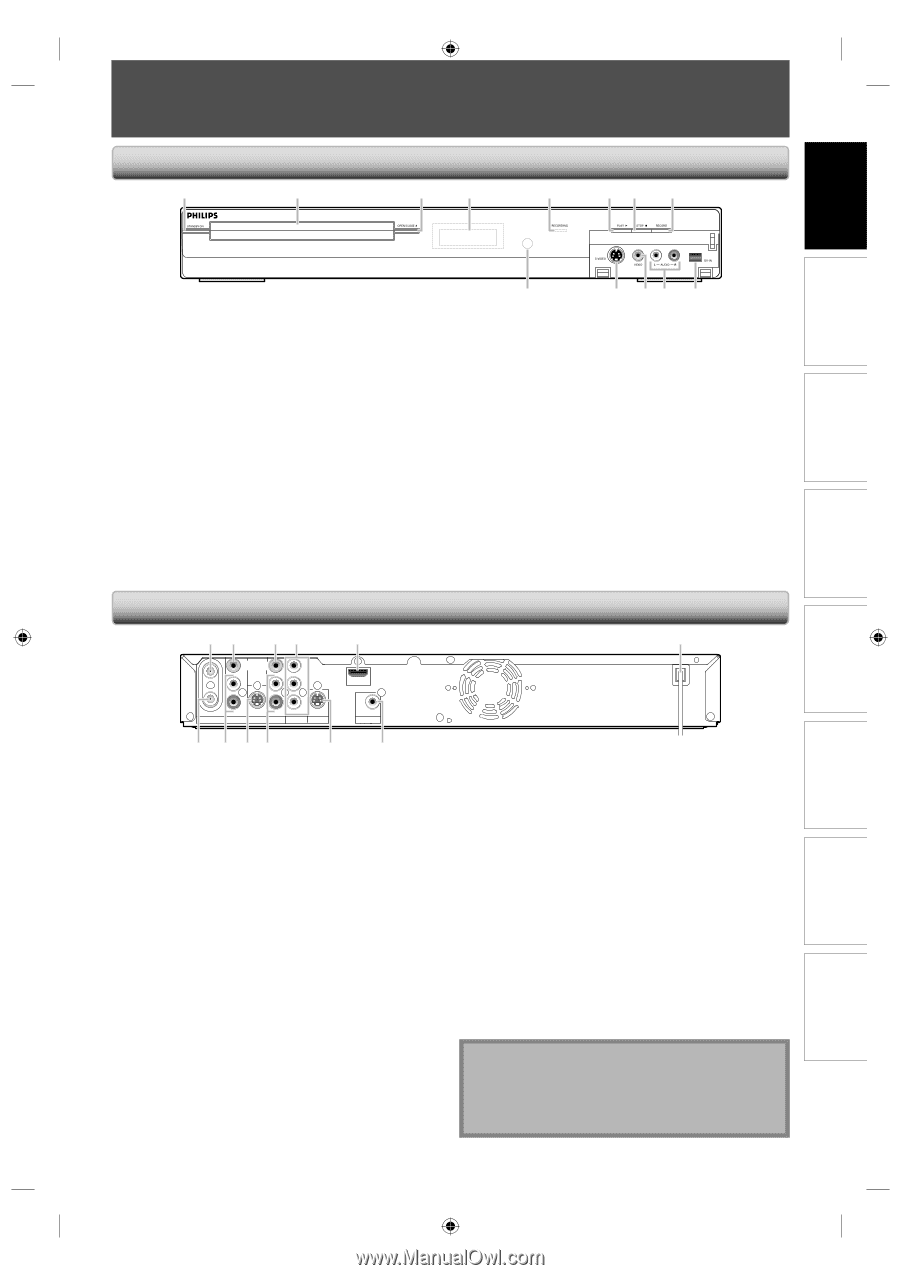
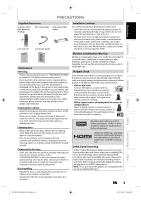
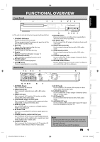
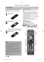
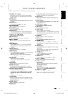
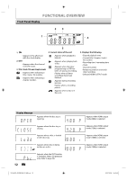
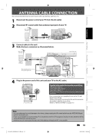
FUNCTIONAL OVERVIEW Front Panel 1 2 3* 4 5 6* 7 8 Introduction Connections Basic Setup Recording Playback (*) The unit can also be turned on by pressing these buttons. 1. STANDBY-ON button Press to turn the unit on and off. If timer programmings have been set, press to set the unit in timer-standby mode. 2. Disc tray Place a disc when opening the disc tray. 3. OPEN/CLOSE A button* Press to open or close the disc tray. 4. Display Refer to "Front Panel Display" on page 12. 5. RECORDING indicator Lights up when recording function works. 6. PLAY B button* Press to start or resume playback. 7. STOP C button Press to stop playback or recording. 13 12 11 10 9 8. RECORD button Press once to start a recording. Press repeatedly to start one-touch timer recording. 9. DV-IN jack (E3) Use to connect the DV output of external device with a DV cable. 10. AUDIO input jacks (E2) Use to connect external device with a RCA audio cable. 11. VIDEO input jack (E2) Use to connect external device with a RCA video cable. 12. S-VIDEO input jack (E2) Use to connect the S-video output of external device with an S-video cable. 13. Infrared sensor window Receive signals from your remote control so that you can control the unit from a distance. Rear Panel 1 2 34 IN VIDEO VIDEO IN OUT Y L PB/CB L R OUT ANTENNA AV IN IN R PR/CR OUT S-VIDEO AV OUT COMPONENT VIDEO OUTPUT S-VIDEO 5 HDMI OUT COAXIAL DIGITAL AUDIO OUTPUT PCM / BITSTREAM 6 12 11 10 9 8 7 1. ANTENNA IN jack Use to connect an antenna. 2. VIDEO IN jack (E1) Use to connect external device with a RCA video cable. 3. VIDEO OUT jack Use to connect a TV monitor, AV receiver or other device with a RCA video cable. 4. COMPONENT VIDEO OUTPUT jacks Use to connect a TV monitor with component video inputs with a component video cable. 5. HDMI OUT jack Use an HDMI cable to connect to a display with an HDMI compatible port. 6. AC Power Cord Connect to a standard AC outlet to supply power to this unit. 7. COAXIAL DIGITAL AUDIO OUTPUT jack Use to connect an AV receiver, Dolby Digital decoder or other device with a digital audio coaxial input jack with a digital audio coaxial cable. 8. S-VIDEO OUT jack Use to connect the S-video input of a TV monitor, AV receiver or other device with an S-video cable. 9. AV OUT jacks Use to connect a TV monitor, AV receiver or other device with a RCA audio cable. 10. S-VIDEO IN jack (E1) Use to connect the S-video output of external device with an S-video cable. 11. AV IN jacks (E1) Use to connect external device with a RCA audio cable. 12. ANTENNA OUT jack Use to connect an RF coaxial cable to pass the signal from the ANTENNA IN to your TV. Note • Do not touch the inner pins of the jacks on the rear panel. Electrostatic discharge may cause permanent damage to the unit. • This unit does not have the RF modulator. EN 9 Editing Function Setup Others E7H42UD_DVDR3506-37_EN.indd 9 2007/12/28 10:52:45
-
 1
1 -
2
-
3
-
 4
4 -
 5
5 -
 6
6 -
 7
7 -
 8
8 -
 9
9 -
 10
10 -
 11
11 -
 12
12 -
 13
13 -
 14
14 -
15
-
16
-
17
-
18
-
19
-
20
-
21
-
22
-
23
-
24
-
25
-
26
-
27
-
28
-
29
-
30
-
31
-
32
-
33
-
34
-
35
-
36
-
37
-
38
-
39
-
40
-
41
-
42
-
43
-
44
-
45
-
46
-
47
-
48
-
49
-
50
-
51
-
52
-
53
-
54
-
55
-
56
-
57
-
58
-
59
-
60
-
61
-
62
-
63
-
64
-
65
-
66
-
67
-
68
-
69
-
70
-
71
-
72
-
73
-
74
-
75
-
76
-
77
-
78
-
79
-
80
-
81
-
82
-
83
-
84
-
85
-
86
-
87
-
88
-
89
-
90
-
91
-
92
-
93
-
94
-
95
-
96
-
97
-
98
-
99
-
100
-
101
-
102
-
103
-
104
-
105
-
106
-
107
-
108
 |
 |