Philips PH-61155 Owners Manual
Philips PH-61155 Manual
 |
View all Philips PH-61155 manuals
Add to My Manuals
Save this manual to your list of manuals |
Philips PH-61155 manual content summary:
- Philips PH-61155 | Owners Manual - Page 1
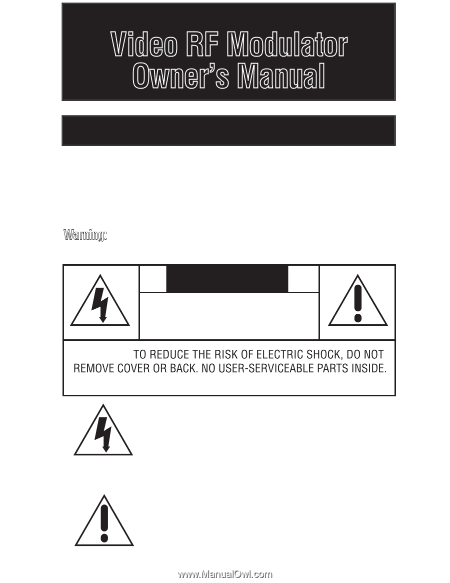
RF Modulator Owner's Manual INTRODUCTION Your Video RF moisture. CAUTION RISK OF ELECTRIC SHOCK. DO NOT OPEN. CAUTION: REFER SERVICING TO QUALIFIED PERSONNEL. This symbol is intended to alert you to the and maintenance instructions are included in the literature accompanying this RF Modulator. - Philips PH-61155 | Owners Manual - Page 2
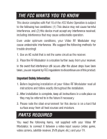
RF Modulator may cause undesirable interference. We suggest the following methods for trouble shooting: 1. Use an AC outlet that is not the same circuit Modulator read all instructions and follow exactly throughout the installation. 2. After installation is complete, keep all instructions in a safe - Philips PH-61155 | Owners Manual - Page 3
PARTS REQUIRED continued • Two 75-ohm coaxial cables with F-type connectors • If your TV does not have a VHF 75-ohm F-connector, you will also need a 75-ohm-to-300-ohm matching transformer • One video shielded cable with RCA Plugs and one audio (stereo) cable with RCA Plugs OR Dubbing Cable for VCR/ - Philips PH-61155 | Owners Manual - Page 4
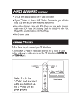
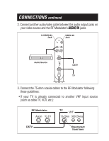
CONNECTIONS continued 2. Connect another audio/video cable between the audio output jacks on your video source and the RF Modulator's AUDIO IN jacks. Jack Audio Source Jack VIDEO L AUDIO OUT R ANT IN Channel 4 3 TO TV CATV 60Hz/4.5W TV 3. Connect the 75-ohm coaxial cables to the RF Modulator - Philips PH-61155 | Owners Manual - Page 5
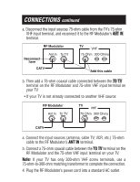
CONNECTIONS continued a. Disconnect the input sources 75-ohm cable from the TV's 75-ohm VHF input terminal, and reconnect it to the RF Modulator's ANT IN terminal. RF Modulator Ant In To TV here CATV TV VHF 75 Ohm 300 Ohms Add this cable b. Then add a 75-ohm coaxial cable connected between the - Philips PH-61155 | Owners Manual - Page 6
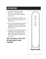
OPERATION 1. Turn on the TV and set it to either Channel 3 or 4, whichever of the two is not used for regular broadcasts in your area. 2. Set the RF Modulator's CHANNEL 3 or 4 switch to the same channel you set on the TV (3 or 4) 3. Turn on the connected video source, the modulator will deliver the - Philips PH-61155 | Owners Manual - Page 7
OPERATION continued 5. To get stereo from your stereo receiver connect L-R stereo audio cables to stereo receiver or home theater. S-VIDEO VIDEO Jack L AUDIO OUT R ANT IN Channel 4 3 TO TV 60Hz/4.5W Output OR Output Output Video Source - Philips PH-61155 | Owners Manual - Page 8
SPECIFICATIONS Video Carrier Output Level RF Output Channels RF Output Impedance Audio Input Impedance 63 dB uV 3 or 4 75 ohms 13 ± 3 k ohms Specifications are typical, individual units might vary. Specifications are subject to change and improvement without notice. Limited Lifetime Warranty The - Philips PH-61155 | Owners Manual - Page 9
Modulador de RF para Vídeo-Manual del Usuario INTRODUCCIÓN Este Modulador de RF para Vídeo está diseñado para convertir señales separadas de audio y de vídeo (provenientes de una videocá - Philips PH-61155 | Owners Manual - Page 10
LA FCC QUIERE QUE UD. SEPA LO SIGUIENTE: Este aparato está en conformidad con la Parte 15 de las normas de la Comisión Federal de Comunicaciones (FCC Rules). Su funcionamiento está sujeto a las siguientes condiciones: (1) este aparato no debe causar interferencia perjudicial, y (2) este aparato debe - Philips PH-61155 | Owners Manual - Page 11
PIEZAS NECESARIAS Para conectar el Modulador de RF de Vídeo entre una fuente de señales de vídeo (juego de vídeo, videocámara, receptor satelital, reproductor de DVDs, etc.) y su televisor, se necesitan los siguientes elementos, que no se suministran con el Modulador. • Dos cables coaxiales de 75 - Philips PH-61155 | Owners Manual - Page 12
CONEXIONES (continuación) 2. Conecte el otro cable de audio/vídeo entre el receptáculos de salida de audio de la fuente de vídeo y el receptáculos rotulado AUDIO IN del Modulador de RF. S-VIDEO IN S-VIDEO VIDEO L AUDIO OUT R ANT IN Channel 4 audiofrecuencia 3 TO TV VIDEO IN por cable 60Hz - Philips PH-61155 | Owners Manual - Page 13
CONNECTIONS continued a. Desconecte del terminal de señales VHF de 75 ohm del televisor el cable de 75 ohm proveniente de las fuentes de señales. Modulador de RF Televisor VHF Ant In To TV 75 Ohm 300 Ohms aquí por cable Agregar este cable b. A continuación, conecte un cable coaxial de 75 - Philips PH-61155 | Owners Manual - Page 14
FUNCIONAMIENTO 1. Encienda el televisor y seleccione el Canal 3 ó 4 (elija el que no se use para teledifusión en su zona). 2. Lleve la llave CHANNEL 4/3 de su Modulador de RF al mismo canal que el televisor (canal 3 ó 4). 3. Encienda la fuente de video conectada, el modulador dará la señal de video - Philips PH-61155 | Owners Manual - Page 15
FUNCIONAMIENTO (continuación) 5. Para obtener sonido estereofónico de su receptor de estéreo, conecte los cables I-D de audio estereofónicos al receptor de estéreo o cine en casa. S-VIDEO VIDEO AUDIO IN L AUDIO OUT R ANT IN Channel 4 3 TO TV audio vídeo O s-vídeo Fuente de vídeo 60Hz/4.5W - Philips PH-61155 | Owners Manual - Page 16
ESPECIFICACIONES Potencia de salida del canal de vídeo Canal de salida de RF Impedancia de salida de RF Impedancia de entrada de audio 63 dB uV 3 ó 4 75 ohms 13 ± 3 k ohms Las especificaciones son generales; pueden haber diferencias entre unidades. Las especificaciones pueden cambiar y mejorar - Philips PH-61155 | Owners Manual - Page 17
Modulateur HF vidéoManuel du propriétaire INTRODUCTION Votre modulateur HF vidéo est conçu pour convertir les signaux audio et vidéo séparés (provenant d'un caméscope, d'un ordinateur, d'un vidéoscope portatif, d'un récepteur de satellite, d'un lecteur de vidéodisque, etc.) en signaux de télévision - Philips PH-61155 | Owners Manual - Page 18
LE FCC VOUDRAIT QUE VOUS SACHIEZ Ce dispositif se conforme à la partie 15 de la réglementation du FCC. Le fonctionnement est soumis aux deux conditions suivantes : (1) Ce dispositif ne doit pas produire de perturbations ou de brouillage nuisibles; (2) il doit absolument accepter tout brouillage ou - Philips PH-61155 | Owners Manual - Page 19
PIÈCES REQUISES Il vous faut les articles suivants, non fournis avec votre modulateur HF vidéo, pour le relier entre une source d'entrée vidéo (jeu vidéo, caméscope, récepteur de satellite, lecteur de vidéodisque, etc.) et votre poste de télévision. • deux câbles coaxiaux 75-ohm avec connecteurs du - Philips PH-61155 | Owners Manual - Page 20
CONNEXIONS (suite) 2. Raccordez un autre câble audio-vidéo entre la prises de sortie audio de votre source vidéo et la prises AUDIO IN du modulateur HF. S-VIDEO IN S-VIDEO VIDEO VIDEO IN L A AUDIO OUT R ANT IN Source audio Channel 4 3 Câblodistributeur TO TV 60Hz/4.5W Poste de télé - Philips PH-61155 | Owners Manual - Page 21
CONNEXIONS (suite) a. Déconnectez de la borne d'entrée VHF 75-ohm du poste de télévision le câble d'entrée 75-ohm de la source d'entrée, puis reconnectez-le à la borne ANT IN du modulateur HF. Modulateur HF Poste de télévision VHF Reconnectez ici Ant In To TV 75 Ohm 300 Ohms Câblodistributeur - Philips PH-61155 | Owners Manual - Page 22
FONCTIONNEMENT 1. Mettez le poste de télévision sous tension et sélectionnez le canal 3 ou 4, selon celui qui ne sert pas aux télédiffusions régulières dans votre région. 2. Réglez le commutateur CHANNEL 4/3 au même canal que vous avez réglé sur le poste de télévision (3 ou 4). 3. Mettre en marche - Philips PH-61155 | Owners Manual - Page 23
FONCTIONNEMENT (suite) 5. Pour obtenir un son stéréophonique à partir du récepteur stéréo, raccorder les câbles stéréo audio gauche et droit du stéréo au récepteur stéréo ou au système de cinéma maison. S-VIDEO VIDEO AUDIO IN L AUDIO OUT R ANT IN Channel 4 3 TO TV audio vidéo OU s-vidéo Source - Philips PH-61155 | Owners Manual - Page 24
FICHE TECHNIQUE Niveau de sortie de la porteuse vidéo Canaux de sortie HF Impédance de sortie HF Impédance d'entrée audio 63 dB uV 3 ou 4 75 ohms 13 ± 3 k ohms Les valeurs sont types; les unités individuelles pourront varier. La fiche technique est susceptible de modifications et(ou) d'amé
-
 1
1 -
 2
2 -
 3
3 -
 4
4 -
 5
5 -
 6
6 -
 7
7 -
8
-
9
-
10
-
11
-
12
-
13
-
14
-
15
-
16
-
17
-
18
-
19
-
20
-
21
-
22
-
23
-
24
 |
 |
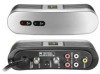
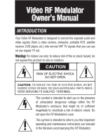
Your Video RF Modulator is designed to convert the separate audio and
video signals (from a video camera, computer, portable VCR, satellite
receiver, DVD player, etc.) into normal VHF TV signals that you can see
on any regular TV set.
INTRODUCTION
This symbol is intended to inform you that important
operating and maintenance instructions are included
in the literature accompanying this RF Modulator.
This symbol is intended to alert you to the presence
of uninsulated dangerous voltage within the RF
Modulator’s enclosure that might be of sufficient
magnitude to constitute a risk of electric shock. Do
not open the RF Modulator’s case.
CAUTION
RISK OF ELECTRIC SHOCK.
DO NOT OPEN.
CAUTION:
REFER SERVICING TO QUALIFIED
PERSONNEL.
W
a
r
n
i
n
g
:
For indoor use only; to reduce risk of fire or shock hazard, do
not expose this product to rain or moisture.
V
i
d
e
o
R
F
M
o
d
u
l
a
t
o
r
O
w
n
e
r
’
s
M
a
n
u
a
l