Philips SRU4000 User manual
Philips SRU4000 Manual
 |
View all Philips SRU4000 manuals
Add to My Manuals
Save this manual to your list of manuals |
Philips SRU4000 manual content summary:
- Philips SRU4000 | User manual - Page 1
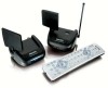
WIRELESS AUDIO/VIDEO with IR Extender Feature Transmisor inalámbrico de Audio y Video con extendedor IR S ENDER OWNER'S MANUAL Manual del Usuario RECEIVER Receptor SENDER Transmisor PRT215-OM_H13957B.pmd 1 PRT215_h13957b-050906 MODEL NO. PRT215 (includes T215 Sender and R215 Receiver) ( - Philips SRU4000 | User manual - Page 2
in your home. The Audio/Video Sender converts the A/V signal from your A/V product into a 2.4 GHz wireless Radio Frequency (RF) signal and transmits it (even through walls) to the Audio/Video Receiver unit. The Audio/Video Receiver converts the signal back to an A/V signal and passes it through - Philips SRU4000 | User manual - Page 3
CONTROLS AND CONNECTIONS Audio/Video Sender Antenna for IR Extender Feature 2.4 GHz Video Antenna 2.4 GHz Channel Switch IR Extender Jack A/V Input Jacks DC6V ON-OFF Switch (on side) Power Supply Jack PRT215-OM_H13957B.pmd 4 4-5 Audio/Video Receiver 2.4 GHz Video Antenna TV Output - Philips SRU4000 | User manual - Page 4
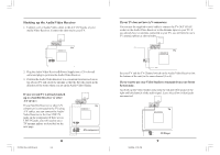
another room, they will probably already be hooked up to the local TV in series (see the diagram to the right). To connect the Audio/Video Sender you just need to identify the last component in the chain and connect its LINE OUT jacks to the Audio - Philips SRU4000 | User manual - Page 5
unit) to the same channel (3 or 4). If you want to use your Video Sender to transmit from your Stereo System only: Just hook up the Video Sender using only the red and white jacks for the right and left channels of the audio signal. Leave the yellow (video) jacks unconnected. 9 9/5/2006, 12:05 PM - Philips SRU4000 | User manual - Page 6
FINE TUNING YOUR SYSTEM The Wireless Audio/Video Sender usually works best with the flat faces of the antennas on the Sender and Receiver units facing each other, see diagram below. Sometimes, however, reflections and other effects in your home may affect the signal so that some adjustment of either - Philips SRU4000 | User manual - Page 7
nuevo a una señal de A/V y la pasa a través de un cable a la entrada COAXIAL de su TV, o a una entrada A/V. El sistema del remitente de Audio/Video también incluye una característica IR. Esto le deja controlar remotamente el producto de A/V con el que el remitente está conectado, del lugar en donde - Philips SRU4000 | User manual - Page 8
DC6V Interruptor de encendido/ apagado (al lado) Entrada para la Fuente de Alimentación PRT215-OM_H13957B.pmd 14-15 14 Receptor de Audio/Video Antena de Vídeo de 2.4 Gigahertz Enchufe de Salida del TV Interruptor de canal de TV (debajo) DC6V Interruptor de encendido/ apagado (al - Philips SRU4000 | User manual - Page 9
SAT Receiver A) Conexiones para un TV con salidas de Audio/Video. SAT Receiver B) Conexiones para un TV sin salidas de Audio/Video. PRT215-OM_H13957B.pmd 16-17 16 3. Conecte la fuente de alimentación del remitente de Audio/Video en un enchufe de pared conveniente de 120 voltios y conecte - Philips SRU4000 | User manual - Page 10
de A/V: Si el receptor de satélite u otro componente de A/V está conectado en el TV usando los cables de A/V, usted puede conectar el receptor de video/ audio en la Línea de entrada libre del componente. Si no hay LÍNEA de entrada disponible, usted necesitará utilizar un divisor de TV y antena seg - Philips SRU4000 | User manual - Page 11
. El telecontrol envía comandos de radiofrecuencia (RF) al remitente de Audio/Video (la unidad con la antena delgada). Este recibe los comandos de RF de . Transmisor A/V DVD Emisor IR VCR LEFT RIGHT DC 12V IR EXT. VIDEO IN AUDIO IN Emisor IR Enchufe del extendedor IR 1. Conecte el enchufe - Philips SRU4000 | User manual - Page 12
an original sales receipt that shows the product name and the date of purchase. For customer support or to obtain warranty service, please call 919-573-7854. THERE ARE NO OTHER EXPRESS OR IMPLIED WARRANTIES. Philips' liability is limited to repair or, at its sole option, replacement of the product
-
 1
1 -
 2
2 -
 3
3 -
 4
4 -
 5
5 -
 6
6 -
 7
7 -
8
-
9
-
10
-
11
-
12
 |
 |

M
ODEL
N
O
. PRT215
(includes T215 Sender and R215 Receiver)
(
incluye el transmisor T215 y el receptor R215)
W
IRELESS
IRELESS
IRELESS
IRELESS
IRELESS
A
A
A
A
A
UDIO
UDIO
UDIO
UDIO
UDIO
/V
/V
/V
/V
/V
IDEO
IDEO
IDEO
IDEO
IDEO
S
S
S
S
S
ENDER
ENDER
ENDER
ENDER
ENDER
with IR Extender Feature
R
ECEIVER
Receptor
OWNER
’
S MANUAL
Manual del Usuario
S
ENDER
Transmisor
Transmisor inalámbrico de Audio
y Video con extendedor IR
PRT215-OM_H13957B.pmd
9/5/2006, 12:05 PM
1
PRT215_h13957b-050906