Pioneer AVH-P3300BT Owner's Manual - Page 85
Installation using the screw, holes on the side of the unit
 |
UPC - 884938123341
View all Pioneer AVH-P3300BT manuals
Add to My Manuals
Save this manual to your list of manuals |
Page 85 highlights
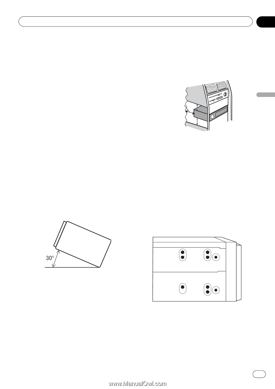
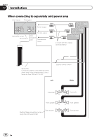
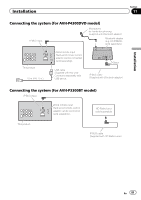
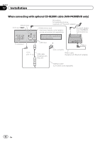
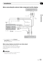
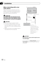
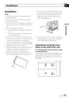
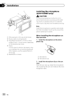
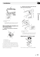
Installation Section 17 Installation Installation Notes ! Check all connections and systems before final installation. ! Do not use unauthorized parts as this may cause malfunctions. ! Consult your dealer if installation requires drilling of holes or other modifications to the vehicle. ! Do not install this unit where: - it may interfere with operation of the vehicle. - it may cause injury to a passenger as a result of a sudden stop. ! Do not install the display where it may (i) obstruct the driver's vision, (ii) impair the performance of any of the vehicle's operating systems or safety features, including air bags, hazard lamp buttons or (iii) impair the driver's ability to safely operate the vehicle. ! The semiconductor laser will be damaged if it overheats. Install this unit away from hot places such as near the heater outlet. ! Optimum performance is obtained when the unit is installed at an angle of less than 30°. ! To ensure proper heat dispersal when using this unit, make sure you leave ample space behind the rear panel and wrap any loose cables so they are not blocking the vents when installing the unit. Leave ample space 5 cm 5 cm 5cm ! To some types of vehicles, this unit cannot be properly installed. In such case, use the optional installation kit (ADT-VA133). Installation using the screw holes on the side of the unit % Fastening the unit to the factory radiomounting bracket. Position the unit so that its screw holes are aligned with the screw holes of the bracket, and tighten the screws at 3 or 4 locations on each side. En 85
-
 1
1 -
2
-
3
-
4
-
5
-
6
-
7
-
8
-
9
-
10
-
11
-
12
-
13
-
14
-
15
-
16
-
17
-
18
-
19
-
20
-
21
-
22
-
23
-
24
-
25
-
26
-
27
-
28
-
29
-
30
-
31
-
32
-
33
-
34
-
35
-
36
-
37
-
38
-
39
-
40
-
41
-
42
-
43
-
44
-
45
-
46
-
47
-
48
-
49
-
50
-
51
-
52
-
53
-
54
-
55
-
56
-
57
-
58
-
59
-
60
-
61
-
62
-
63
-
64
-
65
-
66
-
67
-
68
-
69
-
70
-
71
-
72
-
73
-
74
-
75
-
76
-
77
-
78
-
79
-
 80
80 -
 81
81 -
 82
82 -
 83
83 -
 84
84 -
 85
85 -
 86
86 -
 87
87 -
 88
88 -
 89
89 -
 90
90 -
91
-
92
-
93
-
94
-
95
-
96
-
97
-
98
-
99
-
100
-
101
-
102
-
103
-
104
-
105
-
106
-
107
-
108
 |
 |