Pioneer AVH-P4900DVD Other Manual
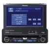
Pioneer AVH-P4900DVD - DVD Player With LCD Monitor Manual
 |
UPC - 012562853161
View all Pioneer AVH-P4900DVD manuals
Add to My Manuals
Save this manual to your list of manuals |
Pioneer AVH-P4900DVD manual content summary:
- Pioneer AVH-P4900DVD | Other Manual - Page 1
MANUAL OF OF AVH-P4900DVD This product conforms to CEMA cord colors. Le code de couleur des câbles utilisé pour ce produit est conforme à CEMA. Printed in Japan Imprimé au Japon UC N STAR N STAR MANUEL D'INSTALLATION Connecting the Units CAUTION: • PIONEER - Pioneer AVH-P4900DVD | Other Manual - Page 2
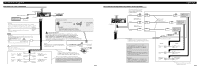
cable IP-BUS input (Blue) Multi-CD player (sold separately) IP-BUS cable This product Yellow/black If you use an equipment with Mute function, wire this lead to the Audio Mute lead on that equipment. If not, keep the Audio Mute lead free of any connections. Red Connect to terminal controlled - Pioneer AVH-P4900DVD | Other Manual - Page 3
Blue DVD Player (e.g. XDV-P6) (sold separately) IP-BUS cable IP-BUS output (Black) To video output (FRONT VIDEO OUTPUT) Blue IP-BUS cable (supplied with TV tuner) Black Blue Hide-away TV tuner (e.g. GEX-P5700TV) (sold separately) AV-BUS cable (supplied with TV tuner) Black Multi-CD Player - Pioneer AVH-P4900DVD | Other Manual - Page 4
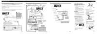
the rear seats to watch the DVD or Video CD. WARNING: • NEVER install the display in a location that enables the Driver to watch the DVD or Video CD while Driving. Installation Note: • Check all connections and systems before final installation. • Do not use unauthorized parts. The use of unautho - Pioneer AVH-P4900DVD | Other Manual - Page 5
ne vous recommande pas d'installer ou d'entretenir vous-même cet écran, car ces travaux peuvent présenter un risque d'électrocution ou d'autres dangers. Confiez tous les travaux d'installation et d'entretien de votre écran au personnel de service Pioneer agréé. • Immobilisez toutes les câblages - Pioneer AVH-P4900DVD | Other Manual - Page 6
IP-BUS (Bleu) Lecteur de CD à chargeur (vendu séparément) conducteur de sourdine audio de cet appareil. Sinon, laisser le fil de mise en sourdine audio sans aucune Dans le cas d'une installation comportant 2 haut-parleurs, ne reliz rien d'autre que les haut-parleurs aux cordons de liaison. Lorsque - Pioneer AVH-P4900DVD | Other Manual - Page 7
iPod) Adaptateur d'iPod (ex. : CD-IB100II) iPod avec connecteur Dock Câble IP-BUS Bleu Port de connexion Dock Connecteur Dock 1,5 m (fourni avec le adaptateur d'iPod) Lecteur de CD à chargeur (vendu séparément) Lorsque vous connectez le lecteur de DVD Fig. 9 • Pour installer la boîte de - Pioneer AVH-P4900DVD | Other Manual - Page 8
DVD ou le Video CD tout en conduisant. Installation Remarque: • Vérifiez toutes les connexions et tous les systèmes avant l'installation tails concernant cette question, reportez-vous aux illustrations qui suivent. Avant d'installer l'appareil • Retirez le cadre et le support. (Fig. 14) Tirez le
-
 1
1 -
 2
2 -
 3
3 -
 4
4 -
 5
5 -
 6
6 -
 7
7 -
8
 |
 |

CAUTION:
•
PIONEER does not recommend that you
install or service your display yourself.
Installing or servicing the product may
expose you to risk of electric shock or
other hazards. Refer all installation and
servicing of your display to authorized
Pioneer service personnel.
•
Secure all wiring with cable clamps or
electrical tape. Do not allow any bare
wiring to remain exposed.
•
Do not drill a hole into the engine com-
partment to connect the yellow lead of
the unit to the vehicle battery. Engine
vibration may eventually cause the insu-
lation to fail at the point where the wire
passes from the passenger compartment
into the engine compartment. Take extra
care in securing the wire at this point.
•
It is extremely dangerous to allow the
display lead to become wound around
the steering column or gearshift. Be sure
to install the display in such a way that it
will not obstruct driving.
•
Make sure that wires will not interfere
with moving parts of the vehicle, such as
the gearshift, parking brake or seat slid-
ing mechanism.
•
Do not shorten any leads. If you do, the
protection circuit may fail to work prop-
erly.
WARNING
•
To avoid the risk of accident and the
potential violation of applicable laws,
the front DVD or TV (sold separate-
ly) feature should never be used
while the vehicle is being driven.
Also, Rear Displays should not be in
a location where it is a visible distrac-
tion to the driver.
•
In some countries or states the view-
ing of images on a display inside a
vehicle even by persons other than
the driver may be illegal. Where such
regulations apply, they must be
obeyed and this unit's DVD features
should not be used.
INSTALLATION MANUAL
MANUEL D’INSTALLATION
<KSNNF> <07B00000>
AVH-P4900DVD
Printed in Japan
Imprimé au Japon
<CRD4195-A> UC
Connecting the Units
ENGLISH
This product conforms to CEMA cord colors.
Le code de couleur des câbles utilisé pour ce produit est
conforme à CEMA.
Note:
•
This unit cannot be installed in a vehicle that
does not have an ACC (accessory) position on
the ignition switch. (Fig. 1)
Fig. 1
•
Use this unit in other than the following condi-
tions could result in fire or malfunction.
—
Vehicles with a 12-volt battery and negative
grounding.
—
Speakers with 50 W (output value) and 4 ohm
to 8 ohm (impedance value).
•
To prevent short-circuit, overheating or malfunc-
tion, be sure to follow the directions below.
—
Disconnect the negative terminal of the battery
before installation.
—
Secure the wiring with cable clamps or adhe-
sive tape. To protect the wiring, wrap adhesive
tape around them where they lie against metal
parts.
—
Place all cables away from moving parts, such
as gear shift and seat rails.
—
Place all cables away from hot places, such as
near the heater outlet.
—
Do not pass the yellow cable through a hole
into the engine compartment to connect to a
battery.
—
Cover any disconnected cable connectors with
insulating tape.
—
Do not remove RCA caps if RCA cables are
not used.
—
Do not shorten any cables.
—
Never cut the insulation of the power cable of
this unit in order to share the power to other
equipment. Current capacity of the cable is
limited.
—
Use a fuse of the rating prescribed.
—
Never wire the speaker negative cable directly
to ground.
—
Never band together multiple speaker’s nega-
tive cables.
•
Control signal is output through blue/white cable
when this unit is powered on. Connect it to an
external power amp’s system remote control or
the vehicle’s auto-antenna relay control terminal
(max. 300 mA, 12 V DC). If the vehicle is
equipped with a glass antenna, connect it to the
antenna booster power supply terminal.
•
Never connect blue/white cable to external power
amp’s power terminal. Also, never connect it to
the power terminal of the auto antenna.
Otherwise, battery drain or malfunction may
result.
•
IP-BUS connectors are color-coded. Be sure to
connect connectors of the same color.
•
Black cable is ground. This cable and other prod-
uct’s ground cable (especially, high-current prod-
ucts such as power amp) must be wired separate-
ly. Otherwise, fire or malfunction may result if
they are accidentally detached.
•
Cord function may differ according to the
product, even if cord color is the same. When
connecting this system, be sure to check all
manuals and connect cords correctly.
No ACC position
ACC position
O
N
S
T
A
R
T
O
F
F
A
C
C
O
N
S
T
A
R
T
O
F
F