Pioneer AVH-P6800DVD Other Manual
Pioneer AVH-P6800DVD - DVD Changer With LCD Monitor Manual
 |
UPC - 012562803548
View all Pioneer AVH-P6800DVD manuals
Add to My Manuals
Save this manual to your list of manuals |
Pioneer AVH-P6800DVD manual content summary:
- Pioneer AVH-P6800DVD | Other Manual - Page 1
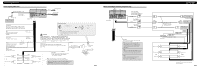
beginning installation. • Refer to the owner's manual for details on connecting the power amp and other units, then make connections correctly. • Secure the wiring with cable clamps or adhesive tape. To protect the wiring, wrap adhesive tape around them where they lie against metal parts. • Route - Pioneer AVH-P6800DVD | Other Manual - Page 2
cord IP-BUS input (Blue) 16 cm Violet/white Refer to Fig. 4. 20 cm AUX input jack 15 cm Antenna cable IP-BUS cable Multi-CD player (sold separately) This product Yellow/black If you use a cellular telephone, connect it via the Audio Mute lead on the cellular telephone. If not, keep the Audio - Pioneer AVH-P6800DVD | Other Manual - Page 3
with the iPod adapter) iPod adapter (e.g. CD-IB100-) iPod with dock connector Dock connector port 1.5 m Dock connector (Supplied with the iPod adapter) Multi-CD player (sold separately) Fig. 6 When connecting with a navigation unit and Bluetooth adapter 26 pin cable input This - Pioneer AVH-P6800DVD | Other Manual - Page 4
DVD or Video CD while Driving. Note: • Before finally installing the unit, connect the wiring temporarily, making sure it is all connected up properly, and the unit and the system work properly. • Use only the parts surface before affixing the velcro tape. Remote control unit Velcro tape (small) ( - Pioneer AVH-P6800DVD | Other Manual - Page 5
être respectée, et les fonctions DVD de cet appareil ne doivent pas être utilisées. Remarque: • Cet appareil est destiné aux véhicules avec une batterie de 12 V, avec pôle négatif à la masse. Avant de l'installer dans un véhicule de loisir, un camion ou un car, vérifier la tension de la - Pioneer AVH-P6800DVD | Other Manual - Page 6
BUT DE DETECTER L'ETAT DE STATIONNEMENT DU VEHICULE ET DOIT ETRE CONNECTE AU COTE ALIMENTATION DU COMMUTATEUR DU FREIN A MAIN. UNE 12V CC). Dans le cas d'une installation comportant 2 haut-parleurs, ne reliz rien d'autre que les haut-parleurs aux cordons de liaison. Lorsque vous raccordez le - Pioneer AVH-P6800DVD | Other Manual - Page 7
parément) 8m Conducteur rallonge (fourni) Violet/blanc Des deux conducteurs connectés au feu de recul, connectez celui pour lequel la tension change iPod) Lecteur de CD à chargeur (vendu séparément) Fig. 6 Lors de la connexion d'une unité de navigation et de l'adaptateur Bluetooth - Pioneer AVH-P6800DVD | Other Manual - Page 8
les images fournies par un DVD ou un Video CD. AVERTISSEMENT: • Veillez à ce que l'écran NE SOIT PAS installé en un endroit tel que encastrée (5 × 6 mm), en fonction de la forme des trous de vis du support. Support de montage radio d'origine Si la languette est gênante, pliez-la. Fig. 12 Vis
-
 1
1 -
 2
2 -
 3
3 -
 4
4 -
 5
5 -
 6
6 -
 7
7 -
8
 |
 |

CAUTION:
•
PIONEER does not recommend that you
install or service your display yourself.
Installing or servicing the product may
expose you to risk of electric shock or
other hazards. Refer all installation and
servicing of your display to authorized
Pioneer service personnel.
•
Secure all wiring with cable clamps or
electrical tape. Do not allow any bare
wiring to remain exposed.
•
Do not drill a hole into the engine com-
partment to connect the yellow lead of
the unit to the vehicle battery. Engine
vibration may eventually cause the insu-
lation to fail at the point where the wire
passes from the passenger compartment
into the engine compartment. Take extra
care in securing the wire at this point.
•
It is extremely dangerous to allow the
display lead to become wound around
the steering column or gearshift. Be sure
to install the display in such a way that it
will not obstruct driving.
•
Make sure that wires will not interfere
with moving parts of the vehicle, such as
the gearshift, parking brake or seat slid-
ing mechanism.
•
Do not shorten any leads. If you do, the
protection circuit may fail to work prop-
erly.
WARNING
•
To avoid the risk of accident and the potential vio-
lation of applicable laws, the front DVD or TV
(sold separately) feature should never be used
while the vehicle is being driven.
Also, Rear
Displays should not be in a location where it is a
visible distraction to the driver.
•
In some countries or states the viewing of images
on a display inside a vehicle even by persons other
than the driver may be illegal. Where such regula-
tions apply, they must be obeyed and this unit's
DVD features should not be used.
INSTALLATION MANUAL
MANUEL D’INSTALLATION
<KNNNF> <06C00000>
AVH-P6800DVD
Printed in Japan
Imprimé au Japon
<CRD4075-A> UC
Connecting the Units
ENGLISH>
Note:
•
This unit is for vehicles with a 12-volt battery and
negative grounding. Before installing it in a recre-
ational vehicle, truck, or bus, check the battery
voltage.
•
To avoid shorts in the electrical system, be sure to
disconnect the
≠
battery cable before beginning
installation.
•
Refer to the owner’s manual for details on
connecting the power amp and other units, then
make connections correctly.
•
Secure the wiring with cable clamps or adhesive
tape. To protect the wiring, wrap adhesive tape
around them where they lie against metal parts.
•
Route and secure all wiring so it cannot touch any
moving parts, such as the gear shift, handbrake and
seat rails. Do not route wiring in places that get
hot, such as near the heater outlet. If the insulation
of the wiring melts or gets torn, there is a danger of
the wiring short-circuiting to the vehicle body.
•
Don’t pass the yellow lead through a hole into the
engine compartment to connect to the battery. This
will damage the lead insulation and cause a very
dangerous short.
•
Do not shorten any leads. If you do, the protection
circuit may fail to work when it should.
•
Never feed power to other equipment by cutting
the insulation of the power supply lead of the unit
and tapping into the lead. The current capacity of
the lead will be exceeded, causing overheating.
•
When replacing the fuse, be sure to only use a fuse
of the rating prescribed on the fuse holder.
•
Since a unique BPTL circuit is employed, never
wire so the speaker leads are directly grounded or
the left and right
≠
speaker leads are common.
•
If the RCA pin jack on the unit will not be used, do
not remove the caps attached to the end of the con-
nector.
•
Speakers connected to this unit must be high-
power with minimum rating of 50 W and imped-
ance of 4 to 8 ohms. Connecting speakers with out-
put and/or impedance values other than those
noted here may result in the speakers
catching fire, emitting smoke or becoming dam-
aged.
•
When this product’s source is switched ON, a con-
trol signal is output through the blue/white lead.
Connect to an external power amp’s system remote
control or the car’s Auto-antenna relay control ter-
minal (max. 300 mA 12 V DC). If the car features
a glass antenna, connect to the antenna booster
power supply terminal.
•
When an external power amp is being used with
this system, be sure not to connect the blue/white
lead to the amp’s power terminal. Likewise, do not
connect the blue/white lead to the power terminal
of the auto-antenna. Such connection could cause
excessive current drain and malfunction.
•
To avoid short-circuit, cover the disconnected lead
with insulating tape. Insulate the unused speaker
leads without fail. There is a possibility of a short-
circuit if the leads are not insulated.
•
To prevent incorrect connection, the input side of
the IP-BUS connector is blue, and the output side
is black. Connect the connectors of the same
colors correctly.
•
This unit cannot be installed in a vehicle that
does not have an ACC (accessory) position on
the ignition switch. (Fig. 1)
Fig. 1
•
The black lead is ground. Please ground this lead
separately from the ground of high-current prod-
ucts such as power amps.
If you ground the products together and the ground
becomes detached, there is a risk of damage to the
products or fire.
No ACC position
ACC position
O
N
S
T
A
R
T
O
F
F
A
C
C
O
N
S
T
A
R
T
O
F
F
•
Cords for this product and those for other products
may be different colors even if they have the same
function. When connecting this product to another
product, refer to the supplied manuals of both
products and connect cords that have the same
function.
This product conforms to CEMA cord colors.
Le code de couleur des câbles utilisé pour ce produit est
conforme à CEMA.