Pioneer AVH-P7480DVD Owner's Manual - Page 142
Connecting the Power Cord of AV Receiver, 12V DC ON/OFF.
 |
View all Pioneer AVH-P7480DVD manuals
Add to My Manuals
Save this manual to your list of manuals |
Page 142 highlights
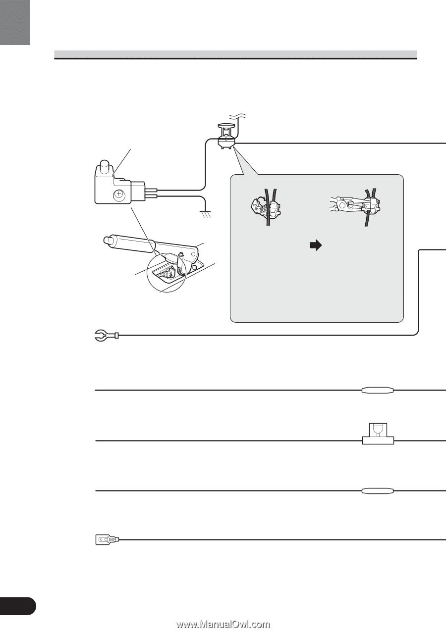
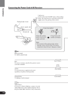
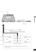
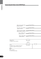
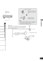
Connecting the Power Cord of AV Receiver Installation Parking brake switch Power supply side Ground side Light green Used to detect the ON/OFF status of the parking brake. This lead must be connected to the power supply side of the parking brake switch. Connection method Clamp the parking brake switch power supply side lead. Clamp firmly with needle-nosed pliers. Note: • The position of the parking brake switch depends on the vehicle model. For details, consult the vehicle Owner's Manual or dealer. Black (ground) To vehicle (metal) body. Red To electric terminal controlled by ignition switch (12V DC) ON/OFF. Yellow To terminal always supplied with power regardless of ignition switch position. Orange/white To lighting switch terminal. Fuse resistor Fuse holder Fuse resistor Yellow/black If you use a cellular telephone, connect it via the Audio Mute lead on the cellular telephone. If not, keep the Audio Mute lead free of any connections. 141
-
 1
1 -
2
-
3
-
4
-
5
-
6
-
7
-
8
-
9
-
10
-
11
-
12
-
13
-
14
-
15
-
16
-
17
-
18
-
19
-
20
-
21
-
22
-
23
-
24
-
25
-
26
-
27
-
28
-
29
-
30
-
31
-
32
-
33
-
34
-
35
-
36
-
37
-
38
-
39
-
40
-
41
-
42
-
43
-
44
-
45
-
46
-
47
-
48
-
49
-
50
-
51
-
52
-
53
-
54
-
55
-
56
-
57
-
58
-
59
-
60
-
61
-
62
-
63
-
64
-
65
-
66
-
67
-
68
-
69
-
70
-
71
-
72
-
73
-
74
-
75
-
76
-
77
-
78
-
79
-
80
-
81
-
82
-
83
-
84
-
85
-
86
-
87
-
88
-
89
-
90
-
91
-
92
-
93
-
94
-
95
-
96
-
97
-
98
-
99
-
100
-
101
-
102
-
103
-
104
-
105
-
106
-
107
-
108
-
109
-
110
-
111
-
112
-
113
-
114
-
115
-
116
-
117
-
118
-
119
-
120
-
121
-
122
-
123
-
124
-
125
-
126
-
127
-
128
-
129
-
130
-
131
-
132
-
133
-
134
-
135
-
136
-
 137
137 -
 138
138 -
 139
139 -
 140
140 -
 141
141 -
 142
142 -
 143
143 -
 144
144 -
 145
145 -
 146
146 -
 147
147 -
148
-
149
-
150
-
151
-
152
-
153
-
154
-
155
-
156
-
157
-
158
-
159
-
160
 |
 |