Pioneer AVH-X5500BHS Owner's Manual - Page 45
Connection, s auto-anten - wiring
 |
View all Pioneer AVH-X5500BHS manuals
Add to My Manuals
Save this manual to your list of manuals |
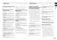
Page 45 highlights
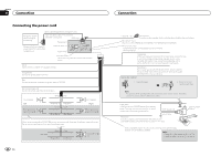
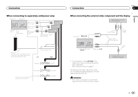
Connection - Secure the wiring with cable clamps or adhesive tape. Wrap adhesive tape around wiring that comes into contact with metal parts to protect the wiring. - Place all cables away from moving parts, such as the shift lever and seat rails. - Place all cables away from hot places, such as near the heater outlet. - Do not connect the yellow cable to the battery by passing it through the hole to the engine compartment. - Cover any disconnected cable connectors with insulating tape. - Do not shorten any cables. - Never cut the insulation of the power cable of this unit in order to share the power with other devices. The current capacity of the cable is limited. - Use a fuse of the rating prescribed. - Never wire the negative speaker cable directly to ground. - Never band together negative cables of multiple speakers. ! When this unit is on, control signals are sent through the blue/white cable. Connect this cable to the system remote control of an external power amp or the vehicle's auto-antenna relay control terminal (max. 300 mA 12 V DC). If the vehicle is equipped with a glass antenna, connect it to the antenna booster power supply terminal. ! Never connect the blue/white cable to the power terminal of an external power amp. Also, never connect it to the power terminal of the auto antenna. Doing so may result in battery drain or a malfunction. Connection Section 25 En 45 English
-
 1
1 -
2
-
3
-
4
-
5
-
6
-
7
-
8
-
9
-
10
-
11
-
12
-
13
-
14
-
15
-
16
-
17
-
18
-
19
-
20
-
21
-
22
-
23
-
24
-
25
-
26
-
27
-
28
-
29
-
30
-
31
-
32
-
33
-
34
-
35
-
36
-
37
-
38
-
39
-
 40
40 -
 41
41 -
 42
42 -
 43
43 -
 44
44 -
 45
45 -
 46
46 -
 47
47 -
 48
48 -
 49
49 -
 50
50 -
51
-
52
-
53
-
54
-
55
-
56
-
57
-
58
-
59
-
60
-
61
-
62
-
63
-
64
-
65
-
66
-
67
-
68
-
69
-
70
-
71
-
72
-
73
-
74
-
75
-
76
-
77
-
78
-
79
-
80
-
81
-
82
-
83
-
84
-
85
-
86
-
87
-
88
-
89
-
90
-
91
-
92
-
93
-
94
-
95
-
96
-
97
-
98
-
99
-
100
-
101
-
102
-
103
-
104
-
105
-
106
-
107
-
108
-
109
-
110
-
111
-
112
-
113
-
114
-
115
-
116
-
117
-
118
-
119
-
120
-
121
-
122
-
123
-
124
-
125
-
126
-
127
-
128
-
129
-
130
-
131
-
132
-
133
-
134
-
135
-
136
-
137
-
138
-
139
-
140
-
141
-
142
-
143
-
144
-
145
-
146
-
147
-
148
-
149
-
150
-
151
-
152
-
153
-
154
-
155
-
156
-
157
-
158
-
159
-
160
-
161
-
162
-
163
-
164
-
165
-
166
-
167
-
168
-
169
-
170
-
171
-
172
-
173
-
174
-
175
-
176
-
177
-
178
-
179
-
180
-
181
-
182
-
183
-
184
-
185
-
186
-
187
-
188
-
189
-
190
-
191
-
192
-
193
-
194
-
195
-
196
-
197
-
198
-
199
-
200
-
201
-
202
-
203
-
204
-
205
-
206
-
207
-
208
-
209
-
210
-
211
-
212
 |
 |