Pioneer AXM-P8000 Other Manual
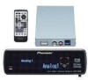
Pioneer AXM-P8000 - Controller Module Manual
 |
UPC - 012562693538
View all Pioneer AXM-P8000 manuals
Add to My Manuals
Save this manual to your list of manuals |
Pioneer AXM-P8000 manual content summary:
- Pioneer AXM-P8000 | Other Manual - Page 1
INSTALLATION MANUAL OF OF AXM-P8000 This product conforms to CEMA cord colors. Le code de couleur des câbles utilisé pour ce produit est conforme à CEMA. Printed in Japan UC N STAR N STAR MANUEL D'INSTALLATION Installation Note: • Before finally installing the - Pioneer AXM-P8000 | Other Manual - Page 2
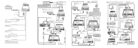
car stereo or other equipment has both speaker output and RCA output, be sure to connect with RCA output. Optical cable (supplied with multi-channel processor) Yellow (FRONT VIDEO OUTPUT) Blue RCA cable (supplied with mulit-DVD player) Multi-channel processor (DEQ-P8000) (sold separately) Multi - Pioneer AXM-P8000 | Other Manual - Page 3
brusque, comme pendant un arrêt d'urgence. Installation de l'unité d'affichage Utilisation du support 1. Fixez le support (A) à l'unité d'affichage. Unité avec pôle négatif à la masse. Avant de l'installer dans un véhicule de loisir, un camion ou un car, vérifier la tension de la batterie. • Afin - Pioneer AXM-P8000 | Other Manual - Page 4
audio sur la téléphone cellulaire. Sinon, laisser le câble de mise en sourdine audio multi-canaux (DEQ-P8000) (vendu séparément) Lecteur de DVD à chargeur (XDV-P90) (vendu séparément) Noir Bleu Noir Noir Jaune (VIDEO télévision) Noir Si l'unité de navigation Pioneer (AVIC-N1) est reliée à cet
-
 1
1 -
 2
2 -
 3
3 -
 4
4
 |
 |
Note:
•
Before finally installing the unit, connect the
wiring temporarily, making sure it is all connect-
ed up properly, and the unit and the system work
properly.
•
Use only the parts included with the unit to
ensure proper installation. The use of unautho-
rized parts can cause malfunctions.
•
Consult with your nearest dealer if installation
requires the drilling of holes or other modifica-
tions of the vehicle.
•
Install the unit where it does not get in the dri-
ver’s way and cannot injure the passenger if there
is a sudden stop, like an emergency stop.
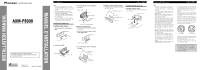
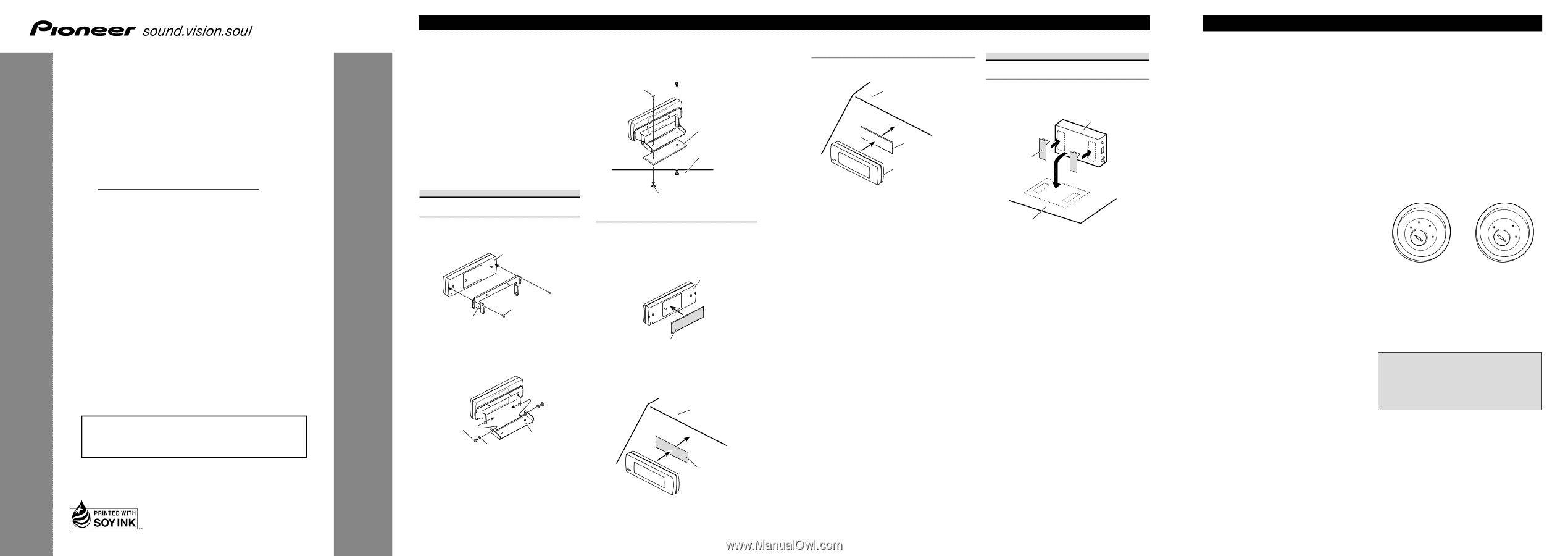
Installing the display unit
Installation using the bracket
1. Attach bracket (A) to the display
unit.
2. Attach bracket (B).
3. Attach the display unit to dashboard
or console.
Installation using Velcro tape
•
Thoroughly wipe off the surface before affixing
the velcro tape.
1. Affix the velcro tape (rough surface)
to the display unit.
2. Attach the display unit to dashboard
or console.
Velcro tape
(soft surface)
Dashboard or
console
Display unit
Velcro tape (rough surface)
Drill 2 to 2.5 mm diameter holes.
Dashboard or
console
Double faced tape
Tapping screw
Bracket (B)
Binding screw
Washer
Display unit
Screw
Bracket (A)
Installation
<ENGLISH>
<KSNNF> <04E00000>
AXM-P8000
Printed in Japan
<CRD3882-
B
> UC
INSTALLATION MANUAL
MANUEL D’INSTALLATION
This product conforms to CEMA cord colors.
Le code de couleur des câbles utilisé pour ce produit
est conforme à CEMA.
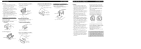
Installation using the double faced tape
•
Thoroughly wipe off the surface before affixing
the double faced tape.
Installing the hide-away unit
Installation using Velcro tape
•
Thoroughly wipe off the surface before affixing
the velcro tape.
Car mat or chassis
Hide-away unit
Velcro tape
Dashboard or console
Display unit
Double faced tape
Note:
•
This unit is for vehicles with a 12-volt battery
and negative grounding. Before installing it in a
recreational vehicle, truck, or bus, check the bat-
tery voltage.
•
To avoid shorts in the electrical system, be sure
to disconnect the
≠
battery cable before begin-
ning installation.
•
Refer to the owner’s manual for details on con-
necting the power amp and other units, then
make connections correctly.
•
Secure the wiring with cable clamps or adhesive
tape. To protect the wiring, wrap adhesive tape
around them where they lie against metal parts.
•
Route and secure all wiring so it cannot touch
any moving parts, such as the gear shift, hand-
brake and seat rails. Do not route wiring in
places that get hot, such as near the heater outlet.
If the insulation of the wiring melts or gets torn,
there is a danger of the wiring short-circuiting to
the vehicle body.
•
Don’t pass the yellow lead through a hole into
the engine compartment to connect to the battery.
This will damage the lead insulation and cause a
very dangerous short.
•
Do not shorten any leads. If you do, the protec-
tion circuit may fail to work when it should.
•
Never feed power to other equipment by cutting
the insulation of the power supply lead of the
unit and tapping into the lead. The current capac-
ity of the lead will be exceeded, causing over-
heating.
•
When replacing fuse, be sure to use only fuse of
the rating prescribed on the fuse holder.
•
To avoid short-circuiting, cover the disconnected
lead with insulating tape. Especially, insulate the
unused speaker leads without fail. There is a pos-
sibility of short-circuiting if the leads are not
insulated.
•
To prevent incorrect connection, the input side of
the IP-BUS connector is blue, and the output side
is black. Connect the connectors of the same col-
ors correctly.
•
If this unit is installed in a vehicle that does not
have an ACC (accessory) position on the ignition
switch, the red lead of the unit should be con-
nected to a terminal coupled with ignition switch
ON/OFF operations. If this is not done, the vehi-
cle battery may be drained when you are away
from the vehicle for several hours.
•
The black lead is ground. Please ground this lead
separately from the ground of high-current prod-
ucts such as power amps.
If you ground the products together and the
ground becomes detached, there is a risk of dam-
age to the products or fire.
•
Cords for this product and those for other prod-
ucts may be different colors even if they have
the same function. When connecting this prod-
uct to another product, refer to the supplied
manuals of both products and connect cords that
have the same function.
Connecting the Units
<ENGLISH>
ACC position
A
C
C
O
N
S
T
A
R
T
O
F
F
O
N
S
T
A
R
T
O
F
F
No ACC position