Pioneer DEH-1700 Other Manual
Pioneer DEH-1700 Manual
 |
UPC - 012562714066
View all Pioneer DEH-1700 manuals
Add to My Manuals
Save this manual to your list of manuals |
Pioneer DEH-1700 manual content summary:
- Pioneer DEH-1700 | Other Manual - Page 1
beginning installation. • Refer to the owner's manual for details on connecting the power amp and other units, then make connections correctly. • Secure the wiring with cable clamps or adhesive tape. To protect the wiring, wrap adhesive tape around them where they lie against metal parts. • Route - Pioneer DEH-1700 | Other Manual - Page 2
é aux véhicules avec une bat- terie de 12 V, avec pôle négatif à la masse. Avant de l'installer dans un véhicule de loisir, un camion ou un car, • Les haut-parleurs connectés à cet appareil doivent être en mesure de supporter une puissance de 45 W, et doivent présenter une impédance comprise entre - Pioneer DEH-1700 | Other Manual - Page 3
función. Cuando se conecta este producto a otro, refiérase a los manuales de ambos productos y conecte los cables que tienen la misma función. culo (12 V CC) ON/OFF. Negro (masa) A la carrocería del veículo (parte metálica). Con un sistema de 2 altavoces, no conecte nada a los hilos de altavoz que - Pioneer DEH-1700 | Other Manual - Page 4
: • Before making a final installation of the unit, tem- porarily connect the wiring to confirm that the connections are correct and the system works properly. • Use only the parts included with the unit to ensure proper installation. The use of unauthorized parts can cause malfunctions. • Consult - Pioneer DEH-1700 | Other Manual - Page 5
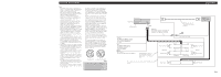
retirer le cadre si la face avant a été déposée. 2. Fixation de l'appareil au support pour le montage de la radio installée par le constructeur. (Fig 8 mm) ou les ves à tête plate (5 × 9 mm), selon le forme des trous de vis sur le support. Fig. 7 10 Support pour le montage de la ra1d2io Fig. 8 - Pioneer DEH-1700 | Other Manual - Page 6
ará si se sobrecalienta, por eso no instale la unidad en un lugar caliente - por Marco Para extraer marco, extienda las partes superior e inferior del marco hacia fuera radio existente T11ornillo T13ablero de instrumentos o consola Fig. 8 Fig. 9 Sobre los tornillos de fijación del panel
-
 1
1 -
 2
2 -
 3
3 -
 4
4 -
 5
5 -
 6
6
 |
 |
Note:
•
This unit is for vehicles with a 12-volt battery and
negative grounding. Before installing it in a recre-
ational vehicle, truck or bus, check the battery
voltage.
•
To avoid shorts in the electrical system, be sure to
disconnect the
≠
battery cable before beginning
installation.
•
Refer to the owner’s manual for details on con-
necting the power amp and other units, then make
connections correctly.
•
Secure the wiring with cable clamps or adhesive
tape. To protect the wiring, wrap adhesive tape
around them where they lie against metal parts.
•
Route and secure all wiring so it cannot touch any
moving parts, such as the gear shift, handbrake and
seat rails. Do not route wiring in places that get
hot, such as near the heater outlet. If the insulation
of the wiring melts or gets torn, there is a danger of
the wiring short-circuiting to the vehicle body.
•
Don’t pass the yellow lead through a hole into the
engine compartment to connect to the battery. This
will damage the lead insulation and cause a very
dangerous short.
•
Do not shorten any leads. If you do, the protection
circuit may fail to work when it should.
•
Never feed power to other equipment by cutting
the insulation of the power supply lead of the unit
and tapping into the lead. The current capacity of
the lead will be exceeded, causing overheating.
•
When replacing the fuse, be sure to only use a fuse
of the rating prescribed on this unit.
•
Since a unique BPTL circuit is employed, never
wire so the speaker leads are directly grounded or
the left and right
≠
speaker leads are common.
If you ground the products together and the ground
becomes detached, there is a risk of damage to the
products or fire.
•
The black lead is ground. Please ground this lead
separately from the ground of high-current prod-
ucts such as power amps.
If you ground the products together and the ground
becomes detached, there is a risk of damage to the
products or fire.
•
Speakers connected to this unit must be high-
power with minimum rating of 45 W and imped-
ance of 4 to 8 ohms. Connecting speakers with out-
put and/or impedance values other than those
noted here may result in the speakers catching fire,
emitting smoke, or becoming damaged.
•
When this product’s source is switched ON, a con-
trol signal is output through the blue/white lead.
Connect to an external power amp’s system remote
control or the car’s Auto-antenna relay control ter-
minal (max. 300 mA 12 V DC). If the car features
a glass antenna, connect to the antenna booster
power supply terminal.
•
When an external power amp is being used with
this system, be sure not to connect the blue/white
lead to the amp’s power terminal. Likewise, do not
connect the blue/white lead to the power terminal
of the auto-antenna. Such connection could cause
excessive current drain and malfunction.
•
To avoid a short-circuit, cover the disconnected
lead with insulating tape. Insulate the unused
speaker leads without fail. There is a possibility of
a short-circuit if the leads are not insulated.
•
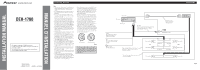
If this unit is installed in a vehicle that does not
have an ACC (accessory) position on the ignition
switch, the red lead of the unit should be connected
to a terminal coupled with ignition switch ON/OFF
operations. If this is not done, the vehicle battery
may be drained when you are away from the vehi-
cle for several hours. (Fig. 1)
Fig. 1
•
Cords for this product and those for other prod-
ucts may be different colors even if they have the
same function. When connecting this product to
another product, refer to the supplied manuals of
both products and connect cords that have the
same function.
No ACC position
ACC position
O
N
S
T
A
R
T
O
F
F
A
C
C
O
N
S
T
A
R
T
O
F
F
<KMMZX> <04H00000>
DEH-1700
Printed in Thailand
Imprimé en Thaïlande
<CRD3907-A/N> UC
+
≠
+
≠
+
≠
+
≠
+
≠
+
≠
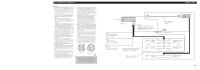
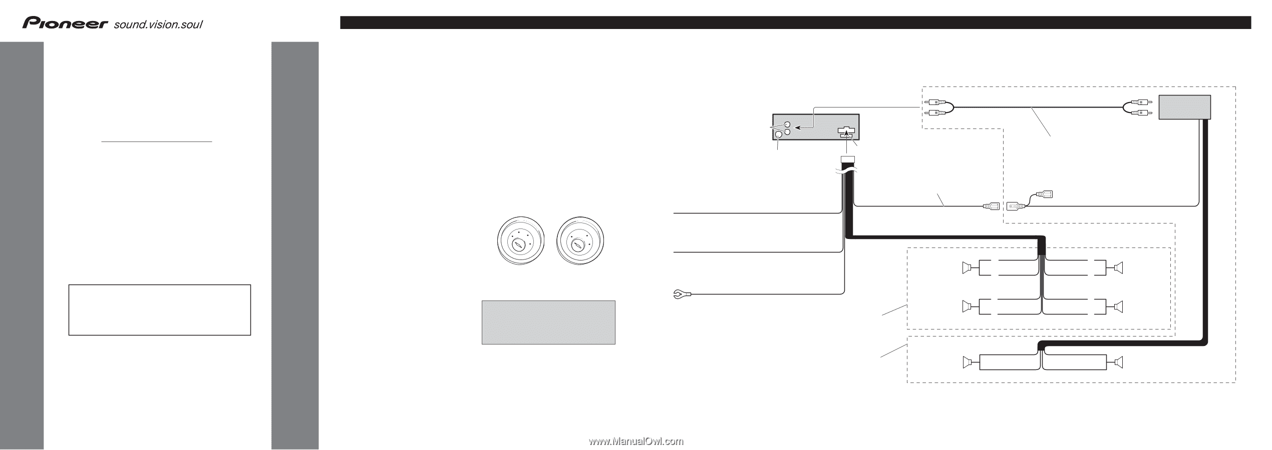
This Product
Blue/white
To system control terminal of the power amp
or Auto-antenna relay control terminal
(max. 300 mA 12 V DC).
Connecting cords
with RCA pin plugs
(sold separately)
System remote control
Rear speaker
Rear speaker
Right
Front speaker
Rear speaker
White
Gray
White/black
Green
Green/black
Gray/black
Violet
Violet/black
Front speaker
Rear speaker
Left
Perform these connections when using
the optional amplifier.
With a 2 speaker system, do not connect
anything to the speaker leads that are not
connected to speakers.
Yellow
To terminal always supplied
with power regardless of
ignition switch position.
Black (ground)
To vehicle (metal) body.
Red
To electric terminal controlled
by ignition switch (12 V DC)
ON/OFF.
Power amp
(sold separately)
Antenna jack
Rear output
Fuse
Fig. 2
Connecting the Units
<ENGLISH>
This product conforms to CEMA cord colors.
Le code de couleur des câbles utilisé pour ce produit est
conforme à CEMA.
Los colores de los cables este producto se conforman
con el código de colores CEMA.
INSTALLATION MANUAL
MANUEL D’INSTALLATION