Pioneer DEH-2400UB Owner's Manual - Page 12
Installation
 |
View all Pioneer DEH-2400UB manuals
Add to My Manuals
Save this manual to your list of manuals |
Page 12 highlights
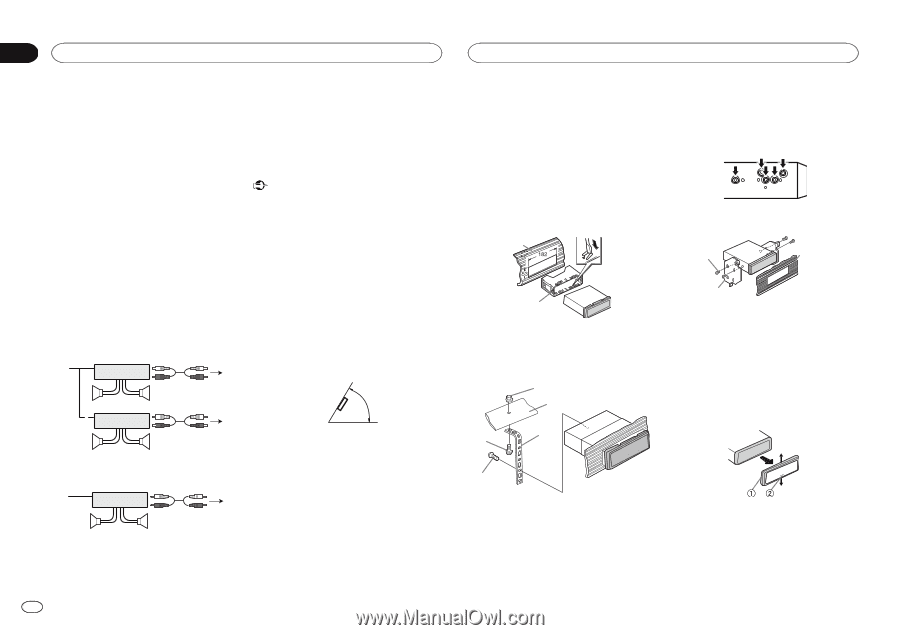
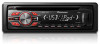
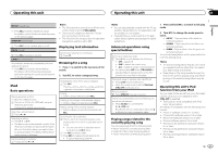
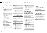
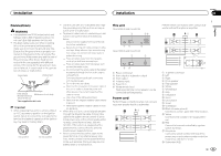
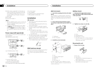
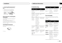
Section 03 Installation Installation j When using a subwoofer of 70 W (2 Ω), be sure to connect the subwoofer to the violet and violet/black leads of this unit. Do not connect anything to the green and green/ black leads. k Not used. l Subwoofer (4 Ω)× 2 Notes ! With a 2 speaker system, do not connect anything to the speaker leads that are not connected to speakers. ! Change the initial setting of this unit. Refer to REAR-SP (rear output setting) on page 9. Refer to PREOUT (preout setting) on page 9. The subwoofer output of this unit is monaural. Power amp (sold separately) Perform these connections when using the optional amplifier. DEH-3400UB and DEH-34UB 1 3 2 4 5 5 3 1 2 6 7 7 DEH-2400UB and DEH-24UB 1 3 2 6 7 7 4 To Front output 5 Front speaker 6 To Rear output or subwoofer output 7 Rear speaker or subwoofer Installation Important ! Check all connections and systems before final installation. ! Do not use unauthorized parts as this may cause malfunctions. ! Consult your dealer if installation requires drilling of holes or other modifications to the vehicle. ! Do not install this unit where: - it may interfere with operation of the vehicle. - it may cause injury to a passenger as a result of a sudden stop. ! The semiconductor laser will be damaged if it overheats. Install this unit away from hot places such as near the heater outlet. ! Optimum performance is obtained when the unit is installed at an angle of less than 60°. 60° DIN front/rear mount This unit can be properly installed using either front-mount or rear-mount installation. Use commercially available parts when installing. 1 System remote control Connect to Blue/white cable. 2 Power amp (sold separately) 3 Connect with RCA cables (sold separately) 12 En DIN Front-mount 1 Insert the mounting sleeve into the dashboard. For installation in shallow spaces, use the supplied mounting sleeve. If there is enough space, use the mounting sleeve that came with the vehicle. DIN Rear-mount 1 Determine the appropriate position where the holes on the bracket and the side of the unit match. 2 Secure the mounting sleeve by using a screwdriver to bend the metal tabs (90°) into place. 2 Tighten two screws on each side. 1 1 3 2 1 Dashboard 2 Mounting sleeve 3 Install the unit as illustrated. 1 2 3 4 2 1 Screw 2 Mounting bracket 3 Dashboard or console ! Use either truss (5 mm × 8 mm) or flush sur- face (5 mm × 9 mm) screws, depending on the bracket screw holes. Removing the unit 1 Remove the trim ring. 5 1 Nut 2 Firewall or metal support 3 Metal strap 4 Screw 5 Screw (M4 × 8) # Make sure that the unit is installed securely in place. An unstable installation may cause skipping or other malfunctions. 1 Trim ring 2 Notched tab ! Releasing the front panel allows easier ac- cess to the trim ring. ! When reattaching the trim ring, point the side with the notched tab down.
-
 1
1 -
2
-
3
-
4
-
5
-
6
-
 7
7 -
 8
8 -
 9
9 -
 10
10 -
 11
11 -
 12
12 -
 13
13 -
 14
14 -
 15
15 -
 16
16 -
 17
17 -
18
-
19
-
20
-
21
-
22
-
23
-
24
-
25
-
26
-
27
-
28
-
29
-
30
-
31
-
32
-
33
-
34
-
35
-
36
-
37
-
38
-
39
-
40
-
41
-
42
-
43
-
44
-
45
-
46
-
47
-
48
-
49
-
50
-
51
-
52
-
53
-
54
-
55
-
56
 |
 |