Pioneer DEH-P5100UB Installation Manual
Pioneer DEH-P5100UB - Radio / CD Manual
 |
UPC - 012562945170
View all Pioneer DEH-P5100UB manuals
Add to My Manuals
Save this manual to your list of manuals |
Pioneer DEH-P5100UB manual content summary:
- Pioneer DEH-P5100UB | Installation Manual - Page 1
CD RECEIVER AUTORADIO CD RADIO CD DEH-P5100UB Installation Manual Manuel d'installation Manual de instalación Printed in Thailand Imprimé en Thaïlande UC Installation Note • Check all connections and systems before final installation. • Do not use unauthorized - Pioneer DEH-P5100UB | Installation Manual - Page 2
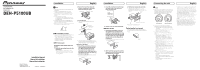
. USB port 2 Use a USB cable to connect the USB storage 20 cm device to the USB port 2. (7-7/8 in.) Pioneer CD-U150E USB cable is also available. For details, consult your dealer. Wired remote input Hard-wired remote control adaptor can be connected (sold separately). IP-BUS input (Blue) Multi-CD - Pioneer DEH-P5100UB | Installation Manual - Page 3
Vis Tableau de bord ou console Support de montage fourni avec la voiture Français Connexions des appareils Français Note • Si cet appareil est installé dans un véhicule sans position ACC (accessoire) sur le commutateur d'allumage, le câble rouge doit être connecté à une borne qui peut détecter - Pioneer DEH-P5100UB | Installation Manual - Page 4
ce conducteur au conducteur de sourdine audio de cet appareil. Sinon, laisser le fil de mise en sourdine audio sans aucune connexion. Télécommande du . Pris USB 2 Utilisez un câble USB pour connecter le périphérique 20 cm à mémoire à la prise USB 2. Le câble Pioneer CD-U150E USB peut aussi - Pioneer DEH-P5100UB | Installation Manual - Page 5
carátula Si no tiene previsto sacar la carátula, ésta se puede fijar con el tornillo suministrado. Tornillo Español Conexión de las unidades Español Nota • Cuando se instale IP-BUS están codificados en colores. Asegúrese de conectar los conectores del mismo color. • El cable negro es para - Pioneer DEH-P5100UB | Installation Manual - Page 6
conductor de silenciamiento de audio en tal equipo. De lo contrario, mantenga el conductor de silenciamiento de audio libre de conexiones. Control 20 cm Puerto USB 2 Utilice un cabo USB para conectar el dispositivo de almacenamiento USB al puerto USB 2. El cable USB CD-U150E Pioneer también está
-
 1
1 -
 2
2 -
 3
3 -
 4
4 -
 5
5 -
 6
6
 |
 |
Installation
English
Installation
English
Connecting the unit
English
Note
• Check all connections and systems before final
installation.
• Do not use unauthorized parts. The use of
unauthorized parts may cause malfunctions.
• Consult with your dealer if installation requires
drilling of holes or other modifications of the
vehicle.
• Do not install this unit where:
— it may interfere with operation of the vehicle.
— it may cause injury to a passenger as a result
of a sudden stop.
• The semiconductor laser will be damaged if it
overheats. Install this unit away from hot places
such as near the heater outlet.
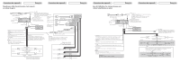
• Optimum performance is obtained when the unit
is installed at an angle of less than 60°.
60°
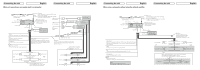
DIN Front/Rear-mount
This unit can be properly installed either from
“Front” (conventional DIN Front-mount) or
“Rear” (DIN Rear-mount installation, utilizing
threaded screw holes at the sides of unit
chassis). For details, refer to the following
installation methods.
DIN Front-mount
Installation with metal strap and
screws
1. Insert the mounting sleeve into the
dashboard.
• When installing in a shallow space, use a
supplied mounting sleeve. If there is enough
space behind the unit, use factory supplied
mounting sleeve.
2. Secure the mounting sleeve by
using a screwdriver to bend the
metal tabs (90°) into place.
Dashboard
Mounting sleeve
53
182
3. Install the unit.
• Use commercially available parts when
installing.
Screw (M4
8)
Screw
Metal strap
Nut
Firewall or
metal support
• Make sure that the unit is installed securely
in place. Unstable installation may cause this
unit to malfunction, such as sound skip.
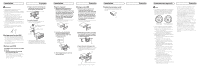
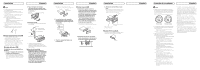
Removing the Unit
1. Extend top and bottom of the trim
ring outwards to remove the trim
ring.
When reattaching the trim
ring, push the trim ring onto the
unit until it clicks. (If the trim ring is
attached upside down, the trim ring
will not fit properly.)
• It becomes easy to remove the trim ring if the
front panel is released.
Trim ring
2. Insert the supplied extraction keys
into both sides of the unit until
they click into place.
3. Pull the unit out of the dashboard.
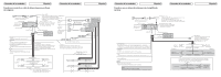
DIN Rear-mount
1.
Extend top and bottom of the trim
ring outwards to remove the trim
ring. When reattaching the trim ring,
push the trim ring onto the unit until
it clicks. (If the trim ring is attached
upside down, the trim ring will not
fit properly.)
• It becomes easy to remove the trim ring if the
front panel is released.
Trim ring
2. Determine the appropriate position
where the holes on the bracket and
the side of the unit match.
3. Tighten two screws on each side.
• Use either truss screws (5 mm × 8 mm)
or flush surface screws (5 mm × 9 mm),
depending on the shape of screw holes in the
bracket.
Factory radio mounting bracket
Screw
Dashboard or Console
Fastening the front panel
If you do not plan to detach the front panel,
the front panel can be fastened with supplied
screw.
Screw
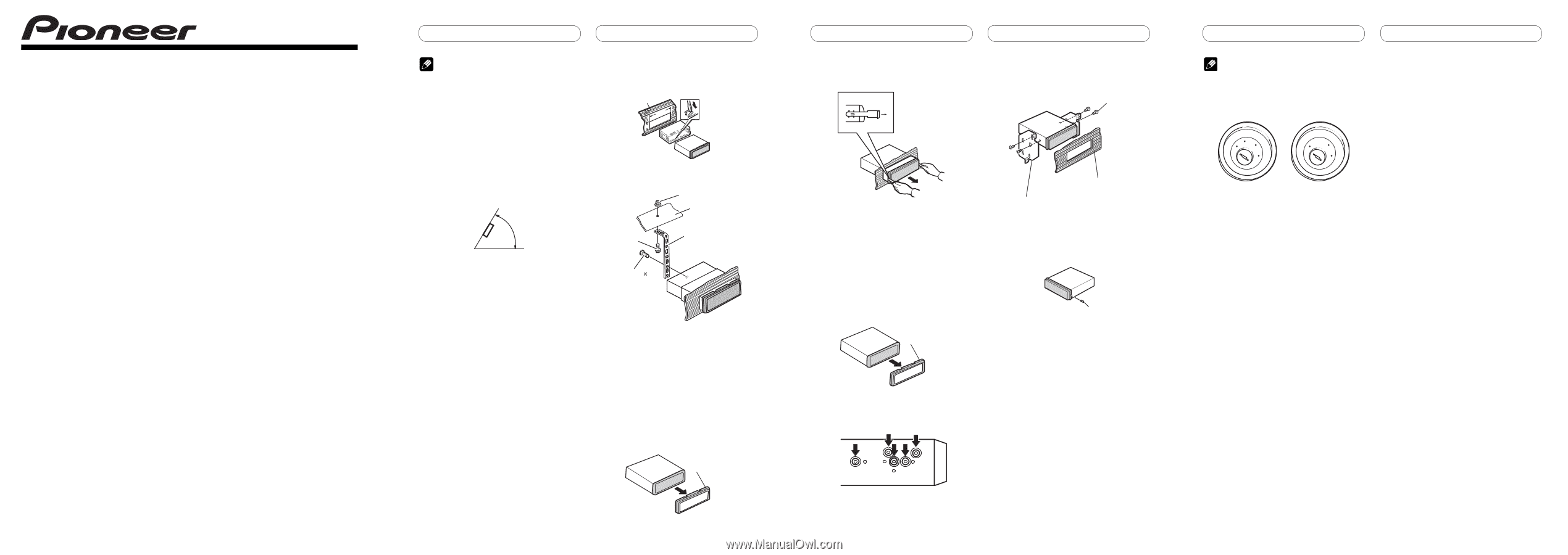
Note
• When this unit is installed in a vehicle without
ACC (accessory) position on the ignition switch,
red cable must be wired to the terminal that
can detect the operation of the ignition key.
Otherwise, battery drain may result.
A
C
C
O
N
S
T
A
R
T
O
F
F
O
N
S
T
A
R
T
O
F
F
ACC position
No ACC position
• Use this unit in other than the following
conditions could result in fire or malfunction.
— Vehicles with a 12-volt battery and negative
grounding.
— Speakers with 50 W (output value) and 4 ohm
to 8 ohm (impedance value).
• To prevent short-circuit, overheating or
malfunction, be sure to follow the directions
below.
— Disconnect the negative terminal of the
battery before installation.
— Secure the wiring with cable clamps or
adhesive tape. To protect the wiring, wrap
adhesive tape around them where they lie
against metal parts.
— Place all cables away from moving parts, such
as gear shift and seat rails.
— Place all cables away from hot places, such
as near the heater outlet.
— Do not pass the yellow cable through a hole
into the engine compartment to connect to a
battery.
— Cover any disconnected cable connectors
with insulating tape.
— Do not shorten any cables.
— Never cut the insulation of the power cable of
this unit in order to share the power to other
equipment. Current capacity of the cable is
limited.
— Use a fuse of the rating prescribed.
— Never wire the speaker negative cable directly
to ground.
— Never band together multiple speaker’s
negative cables.
• Control signal is output through blue/white cable
when this unit is powered on. Connect it to an
external power amp’s system remote control or
the vehicle’s auto-antenna relay control terminal
(max. 300 mA, 12 V DC). If the vehicle is equipped
with a glass antenna, connect it to the antenna
booster power supply terminal.
• Never connect blue/white cable to external
power amp’s power terminal. Also, never connect
it to the power terminal of the auto antenna.
Otherwise, battery drain or malfunction may
result.
• IP-BUS connectors are color-coded. Be sure to
connect connectors of the same color.
• Black cable is ground. This cable and other
product’s ground cable (especially, high-current
products such as power amp) must be wired
separately. Otherwise, fire or malfunction may
result if they are accidentally detached.
<KOKNX>
<08K00000>
Printed in Thailand
Imprimé en Thaïlande
<
QRD3031-A/N
> UC
CD RECEIVER
AUTORADIO CD
RADIO CD
DEH-P5100UB
Installation Manual
Manuel d’installation
Manual de instalación