Pioneer DEH-P6300 Other Manual
Pioneer DEH-P6300 Manual
 |
View all Pioneer DEH-P6300 manuals
Add to My Manuals
Save this manual to your list of manuals |
Pioneer DEH-P6300 manual content summary:
- Pioneer DEH-P6300 | Other Manual - Page 1
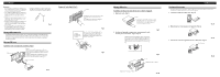
beginning installation. • Refer to the owner's manual for details on connecting the power amp and other units, then make connections correctly. • Secure the wiring with cable clamps or adhesive tape. To protect the wiring, wrap adhesive tape around them where they lie against metal parts. • Route - Pioneer DEH-P6300 | Other Manual - Page 2
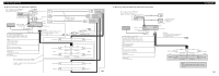
) Power amp (sold separately) System remote control + Front speaker ≠ + Front speaker DEH-P7300. Refer to a Handsfree Telephone Unit's manual (sold separately). MIC terminal 16 cm TEL terminal 16 cm 16 cm 16 cm Multi-CD player (sold separately) Subwoofer output Antenna jack IP-Bus input - Pioneer DEH-P6300 | Other Manual - Page 3
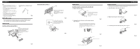
Note: • Before finally installing the unit, connect the wiring temporarily, making sure it is all connected up properly, and the unit and the system work properly. • Use only the parts included with the unit to ensure proper installation. The use of unauthorized parts can cause malfunctions - Pioneer DEH-P6300 | Other Manual - Page 4
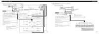
parleurs connectés à cet appareil doivent être tels qu'ils puissent supporter une puissance de 50 W, et que leur impédance soit unité est installée dans un véhicule dont le contacteur d'allumage n'a pas de position ACC (accessoire), le fil rouge de l'unité doit être connecté à une borne couplée aux - Pioneer DEH-P6300 | Other Manual - Page 5
16 cm Cette prise RCA n'est disponible que sur le DEH-P7300. 16 cm Lecteur de CD à chargeur (vendu séparément) Sortie pour haut-parleur installation comportant 2 hautparleurs, ne reliez rien d'autre que les haut-parleurs aux cordons de liaison. Effectuez ces raccordements lorsque l'installation - Pioneer DEH-P6300 | Other Manual - Page 6
aux méthodes de montage illustrées qui suivent. Montage DIN avant Installation avec une bague en caoutchouc (Fig. 5) Tableau de bord 182 53 Support Après avoir introduit le support caoutchouc Vis Dépose de l'unite (Fig. 6) (Fig. au support pour le montage de la radio installée par le constructeur
-
 1
1 -
 2
2 -
 3
3 -
 4
4 -
 5
5 -
 6
6
 |
 |

Note:
•
This unit is for vehicles with a 12-volt battery and
negative grounding. Before installing it in a recre-
ational vehicle, truck, or bus, check the battery
voltage.
•
To avoid shorts in the electrical system, be sure to
disconnect the
≠
battery cable before beginning
installation.
•
Refer to the owner’s manual for details on con-
necting the power amp and other units, then make
connections correctly.
•
Secure the wiring with cable clamps or adhesive
tape. To protect the wiring, wrap adhesive tape
around them where they lie against metal parts.
•
Route and secure all wiring so it cannot touch any
moving parts, such as the gear shift, handbrake
and seat rails. Do not route wiring in places that
get hot, such as near the heater outlet. If the insula-
tion of the wiring melts or gets torn, there is a dan-
ger of the wiring short-circuiting to the vehicle
body.
•
Don’t pass the yellow lead through a hole into the
engine compartment to connect to the battery. This
will damage the lead insulation and cause a very
dangerous short.
•
Do not shorten any leads. If you do, the protection
circuit may fail to work when it should.
•
Never feed power to other equipment by cutting
the insulation of the power supply lead of the unit
and tapping into the lead. The current capacity of
the lead will be exceeded, causing overheating.
•
When replacing fuse, be sure to use only fuse of
the rating prescribed on this unit.
•
Since a unique BPTL circuit is employed, never
wire so the speaker leads are directly grounded or
the left and right
≠
speaker leads are common.
•
Speakers connected to this unit must be high-
power types with minimum rating of 50 W and
impedance of 4 to 8 ohms. Connecting speakers
with output and/or impedance values other than
those noted here may result in the speakers catch-
ing fire, emitting smoke, or becoming damaged.
•
When this product’s source is switched ON, a con-
trol signal is output through the blue/white lead.
Connect to an external power amp’s system remote
control or the car’s Auto-antenna relay control ter-
minal (max. 300 mA 12 V DC). If the car features
a glass antenna, connect to the antenna booster
power supply terminal.
•
When an external power amp is being used with
this system, be sure not to connect the blue/white
lead to the amp’s power terminal. Likewise, do not
connect the blue/white lead to the power terminal
of the auto-antenna. Such connection could cause
excessive current drain and malfunction.
•
To avoid short-circuiting, cover the disconnected
lead with insulating tape. Especially, insulate the
unused speaker leads without fail. There is a possi-
bility of short-circuiting if the leads are not insulat-
ed.
•
To prevent incorrect connection, the input side of
the IP-BUS connector is blue, and the output side
is black. Connect the connectors of the same colors
correctly.
•
If this unit is installed in a vehicle that does not
have an ACC (accessory) position on the ignition
switch, the red lead of the unit should be connected
to a terminal coupled with ignition switch ON/OFF
operations. If this is not done, the vehicle battery
may be drained when you are away from the vehi-
cle for several hours. (Fig. 1)
Fig. 1
•
The black lead is ground. Please ground this lead
separately from the ground of high-current prod-
ucts such as power amps.
If you ground the products together and the ground
becomes detached, there is a risk of damage to the
products or fire.
•
Cords for this product and those for other products
may be different colors even if they have the same
function. When connecting this product to another
product, refer to the supplied Installation manuals
of both products and connect cords that have the
same function.
No ACC position
ACC position
O
N
S
T
A
R
T
O
F
F
A
C
C
O
N
S
T
A
R
T
O
F
F
INSTALLATION MANUAL
MANUEL D’INSTALLATION
<KICFF/00L00000>
DEH-P7300
DEH-P6300
Printed in Thailand
Imprimé en Thaïlande
<CRD3383-A/N> UC
Connecting the Units
<ENGLISH>
This product conforms to CEMA cord colors.
Le code de couleur des câbles utilisé pour ce produit est
conforme à CEMA.