Pioneer DEH-P790BT Other Manual
Pioneer DEH-P790BT - Premier Radio / CD Manual
 |
UPC - 012562853208
View all Pioneer DEH-P790BT manuals
Add to My Manuals
Save this manual to your list of manuals |
Pioneer DEH-P790BT manual content summary:
- Pioneer DEH-P790BT | Other Manual - Page 1
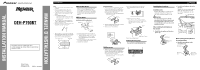
INSTALLATION MANUAL DEH-P790BT This product conforms to CEMA cord colors. Le code de couleur des câbles utilisé pour ce produit est conforme à CEMA. Printed in Thailand Imprimé en Thaïlande UC MANUEL D'INSTALLATION Installation Note: • Check all connections - Pioneer DEH-P790BT | Other Manual - Page 2
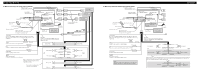
installation. - Secure the wiring with cable clamps or adhesive tape. To protect the wiring, wrap adhesive tape around them where they lie against metal parts. - Place all cables away from moving parts Connect it to an external power amp's system remote control or the vehicle's auto-antenna relay - Pioneer DEH-P790BT | Other Manual - Page 3
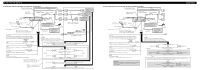
(7-1/8 in) IP-BUS input (Blue) AUX jack (3.5 ø) Use a stereo mini plug cable to connect with auxiliary equipment. 4 m (13 ft. 1 in.) Microphone IP-BUS cable Multi-CD player (sold separately) Yellow/black If you use an equipment with Mute function, wire this lead to the Audio Mute lead on that - Pioneer DEH-P790BT | Other Manual - Page 4
de bord ou console Support de montage fourni avec la voiture Fixation du panneau avant Si vous ne prévoyez pas de détacher le panneau avant, il peut être fixé avec la vis fournie. Vis Garniture Installation du microphone Remarques sur l'installation Installez et orientez le microphone à un endroit - Pioneer DEH-P790BT | Other Manual - Page 5
d'impédance). • Pour éviter tout court-circuit, surchauffe ou mauvais fonctionnement, assurez-vous de suivre les instructions ci-dessous. - Déconnectez la borne négative de la batterie avant l'installation. - Fixez solidement les câbles avec des serrecâbles ou du ruban adhésif. Pour protéger le - Pioneer DEH-P790BT | Other Manual - Page 6
OUTPUT) 23 cm 15 cm 15 cm Entrée microphone Prise d'antenne 15 cm iPod avec connecteur Dock Connecteur Dock Port de connexion Dock Microphone Câble d'interface Entrée de télécommande câblée Un adaptateur de télécommande câblée peut être connecté (vendu séparément). Câble IP-BUS Lecteur de CD
-
 1
1 -
 2
2 -
 3
3 -
 4
4 -
 5
5 -
 6
6
 |
 |
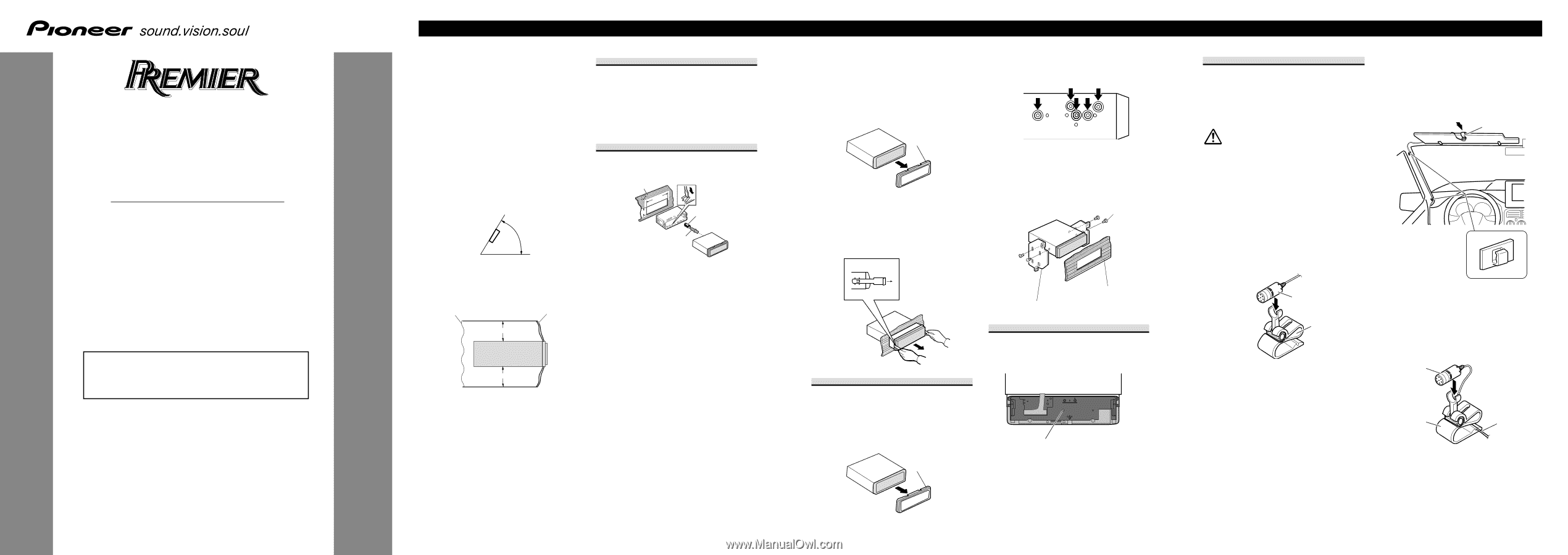
Installing the microphone
Installation notes
Install the microphone in a position and ori-
entation that will enable it to pick up the
voice of the person operating the system.
CAUTION
It is extremely dangerous to allow the
microphone lead to become wound around
the steering column or gearstick. Be sure
to install the unit in such a way that it will
not obstruct driving.
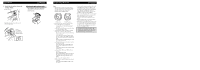
When installing the microphone on
the sun visor
1.
Install the microphone on the micro-
phone clip.
2.
Install the microphone clip on the
sun visor.
With the sun visor up, install the micro-
phone clip. (Lowering the sun visor
reduces the recognition rate for voice
operations.)
When installing the microphone on
the steering column
1.
Install the microphone on the
microphone clip.
Installation
ENGLISH
Note:
•
Check all connections and systems before final
installation.
•
Do not use unauthorized parts. The use of
unauthorized parts may cause malfunctions.
•
Consult with your dealer if installation requires
drilling of holes or other modifications of the
vehicle.
•
Do not install this unit where:
—
it may interfere with operation of the vehicle.
—
it may cause injury to a passenger as a result
of a sudden stop.
•
The semiconductor laser will be damaged if it
overheats. Install this unit away from hot places
such as near the heater outlet.
•
Optimum performance is obtained when the unit
is installed at an angle of less than 60°.
•
When installing, to ensure proper heat dispersal
when using this unit, make sure you leave ample
space behind the rear panel and wrap any loose
cables so they are not blocking the vents.
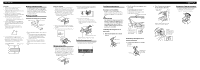
DIN Front/Rear-mount
This unit can be properly installed either from
“Front” (conventional DIN Front-mount) or
“Rear” (DIN Rear-mount installation, utilizing
threaded screw holes at the sides of unit chassis).
For details, refer to the following installation
methods.
DIN Front-mount
Installation with the rubber bush
1.
Insert the mounting sleeve into the dashboard.
•
When installing in a shallow space, use a sup-
plied mounting sleeve. If there is enough
space behind the unit, use factory supplied
mounting sleeve.
2.
Secure the mounting sleeve by using a screwdriv-
er to bend the metal tabs (90°) into place.
3.
Install the unit as illustrated.
53
53
1
1
182
182
10 cm (3-7/8 in.)
10 cm (3-7/8 in.)
60
°
Dashboard
Mounting sleeve
Rubber bush
Screw
Removing the Unit
1.
Extend top and bottom of the trim ring outwards
to remove the trim ring. When reattaching the
trim ring, push the trim ring onto the unit until it
clicks. (If the trim ring is attached upside down,
the trim ring will not fit properly.)
•
It becomes easy to remove the trim ring if the
front panel is released.
2.
Insert the supplied extraction keys into both sides
of the unit until they click into place.
3.
Pull the unit out of the dashboard.
DIN Rear-mount
1.
Extend top and bottom of the trim ring outwards
to remove the trim ring. When reattaching the
trim ring, push the trim ring onto the unit until it
clicks. (If the trim ring is attached upside down,
the trim ring will not fit properly.)
•
It becomes easy to remove the trim ring if the
front panel is released.
2.
Determine the appropriate position where the
holes on the bracket and the side of the unit
match.
3.
Tighten two screws on each side.
•
Use either truss screws (5 mm
×
8 mm) or
flush surface screws (5 mm
×
9 mm), depend-
ing on the shape of screw holes in the
bracket.
Fastening the front panel
If you do not plan to detach the front panel, the
front panel can be fastened with supplied screw.
Trim ring
Screw
Dashboard or Console
Factory radio mounting bracket
Screw
<KMINX> <06L00000>
DEH-P790BT
Printed in Thailand
Imprimé en Thaïlande
<CRD4209-A/N> UC
This product conforms to CEMA cord colors.
Le code de couleur des câbles utilisé pour ce produit est
conforme à CEMA.
INSTALLATION MANUAL
MANUEL D’INSTALLATION
Microphone
Microphone
clip
Microphone clip
Clamps
Use clamps to secure
the lead where neces-
sary inside the vehi-
cle.
Microphone
Microphone
clip
Fit the micro-
phone lead into
the groove.
Trim ring
Leave ample space
Dashboard