Pioneer DEH-P800PRS Other Manual
Pioneer DEH-P800PRS - Premier Radio / CD Manual
 |
UPC - 012562883724
View all Pioneer DEH-P800PRS manuals
Add to My Manuals
Save this manual to your list of manuals |
Pioneer DEH-P800PRS manual content summary:
- Pioneer DEH-P800PRS | Other Manual - Page 1
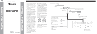
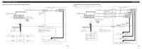
IP-BUS input (Blue) Jack for the Wired Remote Control Adaptors Please see the Instruction Manual for the Wired Remote Control Adaptors (sold separately). IP-BUS cable Multi-CD player (sold separately) Blue/white To system control terminal of the power amp or Auto-antenna relay - Pioneer DEH-P800PRS | Other Manual - Page 2
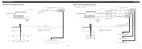
internal amp is turned off. For more details, refer to operation manual. 23 cm (9 in.) Antenna jack 15 cm (5-7/8 in.) Subwoofer speaker ≠ + Rear speaker ≠ System remote control Blue/white To system control terminal of the power amp or Auto-antenna relay control terminal (max. 300 mA 12 V DC - Pioneer DEH-P800PRS | Other Manual - Page 3
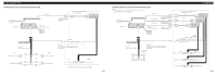
unit's internal amp is turned off. For more details, refer to operation manual. 23 cm (9 in.) Antenna jack 15 cm (5-7/8 in.) 15 cm ≠ FL + FL - RL + RL - System remote control Blue/white To system control terminal of the power amp or Auto-antenna relay control terminal (max. 300 mA 12 V DC). FR + - Pioneer DEH-P800PRS | Other Manual - Page 4
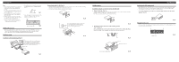
parts included with the unit to ensure proper installation. The use of unauthorized parts can cause malfunctions. • Consult with your nearest dealer if installation Fastening the unit to the factory radio mounting bracket. (Fig. 13) microprocessor. (Refer to operation manual.) • Use a thin standard - Pioneer DEH-P800PRS | Other Manual - Page 5
aux véhicules avec une batterie de 12 V, avec pôle négatif à la masse. Avant de l'installer appareil doivent être en mesure de supporter une puissance de 50 W, et doivent fonction de TA&EQ automatique est en service, assurez-vous de régler la Câble IP-BUS Lecteur de CD à chargeur (vendu séparément - Pioneer DEH-P800PRS | Other Manual - Page 6
• Si vous utilisez ce type de connexion, nous recommandons de mettre hors service l'amplificateur interne. Pour plus de détails, reportez-vous au mode d'emploi vous le figure 2.) FL + FL - RL + RL - Câbles de liaison aux haut-parleurs Non utilisé. Bleu/blanc Vers la borne de commande à distance de - Pioneer DEH-P800PRS | Other Manual - Page 7
vous utilisez ce type de connexion, nous recommandons de mettre hors service l'amplificateur interne. Pour plus de détails, reportez-vous au à distance de l'amplificateur de puissance ou vers la borne Câbles de liaison aux haut-parleurs de commande du relais de l'antenne motorisée (max. 300 mA, - Pioneer DEH-P800PRS | Other Manual - Page 8
aux méthodes de montage illustrées qui suivent. Montage DIN avant Installation avec une bague en caoutchouc (Fig. 9) Tableau de bord 182 53 Support Après avoir introduit le support 12 2. Fixation de l'appareil au support pour le montage de la radio installée par le constructeur. (Fig. 13) (Fig.
-
 1
1 -
 2
2 -
 3
3 -
 4
4 -
 5
5 -
 6
6 -
 7
7 -
8
 |
 |

Note:
•
This unit is for vehicles with a 12-volt battery and
negative grounding. Before installing it in a recre-
ational vehicle, truck, or bus, check the battery
voltage.
•
To avoid shorts in the electrical system, be sure to
disconnect the
≠
battery cable before beginning
installation.
•
Refer to the owner’s manual for details on con-
necting the power amp and other units, then make
connections correctly.
•
Secure the wiring with cable clamps or adhesive
tape. To protect the wiring, wrap adhesive tape
around them where they lie against metal parts.
•
Route and secure all wiring so it cannot touch any
moving parts, such as the gear shift, handbrake and
seat rails. Do not route wiring in places that get hot,
such as near the heater outlet. If the insulation of
the wiring melts or gets torn, there is a danger of
the wiring short-circuiting to the vehicle body.
•
Don’t pass the yellow lead through a hole into the
engine compartment to connect to the battery.
This will damage the lead insulation and cause a
very dangerous short.
•
Do not shorten any leads. If you do, the protection
circuit may fail to work when it should.
•
Never feed power to other equipment by cutting
the insulation of the power supply lead of the unit
and tapping into the lead. The current capacity of
the lead will be exceeded, causing overheating.
•
When replacing the fuse, be sure to only use a
fuse of the rating prescribed on the fuse holder.
•
Since a unique BPTL circuit is employed, never
wire so the speaker leads are directly grounded
or the left and right
≠
speaker leads are common.
•
If the RCA pin jack on the unit will not be used,
do not remove the caps attached to the end of the
connector.
•
Speakers connected to this unit must be high-
power with minimum rating of 50 W and imped-
ance of 4 to 8 ohms. Connecting speakers with
output and/or impedance values other than those
noted here may result in the speakers catching
fire, emitting smoke or becoming damaged.
•
When connecting tweeters, please confirm the
tweeter’s usable frequency range. When you set
the cut-off frequency, set higher than the lowest
usable frequency of the tweeter.
•
Auto TA uses higher range than 10 kHz for mea-
surement. Therefore, using the tweeter that cannot
reproduce 10 kHz frequency range may damage
the tweeter. When Auto TA&EQ is operated, be
sure to set the appropriate cut-off frequency. Also,
use the tweeter that can reproduce 10 kHz at the
lowest usable frequency.
•
When this product’s source is switched ON, a
control signal is output through the blue/white
lead. Connect to an external power amp’s system
remote control or the car’s Auto-antenna relay
control terminal (max. 300 mA 12 V DC). If the
car features a glass antenna, connect to the anten-
na booster power supply terminal.
•
When an external power amp is being used with
this system, be sure not to connect the blue/white
lead to the amp’s power terminal. Likewise, do
not connect the blue/white lead to the power ter-
minal of the auto-antenna. Such connection could
cause excessive current drain and malfunction.
•
To avoid a short-circuit, cover the disconnected
lead with insulating tape. Insulate the unused
speaker leads without fail. There is a possibility of
a short-circuit if the leads are not insulated.
•
To prevent incorrect connection, the input side of
the IP-BUS connector is blue, and the output side
is black. Connect the connectors of the same col-
ors correctly.
•
If this unit is installed in a vehicle that does not
have an ACC (accessory) position on the ignition
switch, the red lead of the unit should be connect-
ed to a terminal coupled with ignition switch
ON/OFF operations. If this is not done, the vehi-
cle battery may be drained when you are away
from the vehicle for several hours. (Fig. 1)
Fig. 1
•
The black lead is ground. Please ground this lead
separately from the ground of high-current prod-
ucts such as power amps.
If you ground the products together and the
ground becomes detached, there is a risk of dam-
age to the products or fire.
No ACC position
ACC position
O
N
S
T
A
R
T
O
F
F
A
C
C
O
N
S
T
A
R
T
O
F
F
INSTALLATION MANUAL
MANUEL D’INSTALLATION
<KMMZX> <07J00000>
DEH-P800PRS
Printed in Thailand
Imprimé en Thaïlande
<CRD4266-A/N> UC
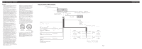
Connecting the Units
<ENGLISH>
Fig. 2
Power cable connection diagram
Fuse holder
(10 A)
Antenna jack
This product
Jack for the Wired Remote Control Adaptors
Please see the Instruction Manual for the
Wired Remote Control Adaptors (sold separately).
Fuse resistor
IP-BUS cable
Multi-CD player
(sold separately)
RCA cable connector
(Refer to Fig. 3 to 6.)
+
≠
+
≠
+
≠
+
≠
Left
Right
With a 2 speaker system, do not
connect anything to the speaker leads
that are not connected to speakers.
Yellow/black
If you use an equipment with Mute
function, wire this lead to the Audio
Mute lead on that equipment.
If not, keep the Audio Mute lead free of
any connections.
Translucent with yellow stripe
To terminal always supplied with
power regardless of ignition switch
position.
Red
To electric terminal controlled by
ignition switch (12 V DC) ON/OFF.
Orange/white
To lighting switch terminal.
Black (ground)
To vehicle (metal) body.
FR +
FR
–
RR +
RR
–
FL +
FL
–
RL +
RL
–
Blue/white
To system control terminal of the power amp or
Auto-antenna relay control terminal (max. 300
mA 12 V DC).
Front speaker
or
Middle range speaker
15 cm
(5-7/8 in.)
Fuse resistor
Front speaker
or
Middle range speaker
Rear speaker
or
High range speaker
Rear speaker
or
High range speaker
Speaker leads
(For more details, refer to Fig. 3 to 6.)
IP-BUS input
(Blue)