Pioneer DEH-P80MP Operation Manual - Page 71
Connecting the Units, <ENGLISH>
 |
View all Pioneer DEH-P80MP manuals
Add to My Manuals
Save this manual to your list of manuals |
Page 71 highlights
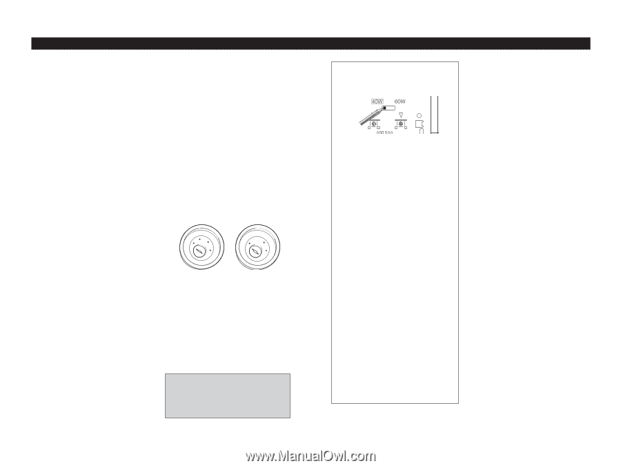
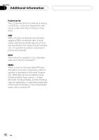
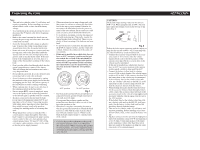
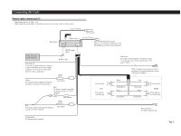
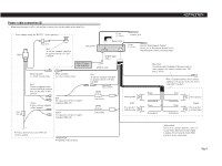
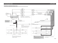
Connecting the Units Note: • This unit is for vehicles with a 12-volt battery and negative grounding. Before installing it in a recreational vehicle, truck, or bus, check the battery voltage. • To avoid shorts in the electrical system, be sure to disconnect the ≠ battery cable before beginning installation. • Refer to the owner's manual for details on connecting the power amp and other units, then make connections correctly. • Secure the wiring with cable clamps or adhesive tape. To protect the wiring, wrap adhesive tape around them where they lie against metal parts. • Route and secure all wiring so it cannot touch any moving parts, such as the gear shift, handbrake and seat rails. Do not route wiring in places that get hot, such as near the heater outlet. If the insulation of the wiring melts or gets torn, there is a danger of the wiring short-circuiting to the vehicle body. • Don't pass the yellow lead through a hole into the engine compartment to connect to the battery. This will damage the lead insulation and cause a very dangerous short. • Do not shorten any leads. If you do, the protection circuit may fail to work when it should. • Never feed power to other equipment by cutting the insulation of the power supply lead of the unit and tapping into the lead. The current capacity of the lead will be exceeded, causing overheating. • When replacing fuse, be sure to use only fuse of the rating prescribed on the fuse holder. • Since a unique BPTL circuit is employed, never wire so the speaker leads are directly grounded or the left and right ≠ speaker leads are common. • Speakers connected to this unit must be highpower types with minimum rating of 40 W and impedance of 4 to 8 ohms. Connecting speakers with output and/or impedance values other than those noted here may result in the speakers catching fire, emitting smoke or becoming damaged. • When this product's source is switched ON, a control signal is output through the blue/white lead. Connect to an external power amp's system remote control or the car's Auto-antenna relay control terminal (max. 300 mA 12 V DC). If the car features a glass antenna, connect to the antenna booster power supply terminal. • When an external power amp is being used with this system, be sure not to connect the blue/white lead to the amp's power terminal. Likewise, do not connect the blue/white lead to the power terminal of the auto-antenna. Such connection could cause excessive current drain and malfunction. • To avoid short-circuiting, cover the disconnected lead with insulating tape. Especially, insulate the unused speaker leads without fail. There is a possibility of short-circuiting if the leads are not insulated. • To prevent incorrect connection, the input side of the IP-BUS connector is blue, and the output side is black. Connect the connectors of the same colors correctly. • If this unit is installed in a vehicle that does not have an ACC (accessory) position on the ignition switch, the red lead of the unit should be connected to a terminal coupled with ignition switch ON/OFF operations. If this is not done, the vehicle battery may be drained when you are away from the vehicle for several hours. (Fig.1) F ACC O F O OF OF N STAR N STAR T T ACC position No ACC position Fig. 1 • The black lead is ground. Please ground this lead separately from the ground of high-current products such as power amps. If you ground the products together and the ground becomes detached, there is a risk of damage to the products or fire. • When there is no place surrounding this unit in which to ground and you wish to extend the black lead, use a cable with the same or greater thickness (official conductor area of 3.0mm2) as the black lead and connect firmly to a metal portion of the vehicle. • Cords for this product and those for other products may be different colors even if they have the same function. When connecting this product to another product, refer to the supplied manuals of both products and connect cords that have the same function. CAUTION: The default output settings values for this unit are 40W × 4ch. When using this unit at 60W × 4ch you must adjust the settings switch on the bottom of this unit. (Fig. 2) Fig. 2 Follow the below upon connecting with the output settings for this unit set at 60W × 4ch. Connecting with any other method may result in malfunction. • Connect the accessory (long red lead) to an acces- sory circuit of 10A or more when the vehicle engine switch is set to the ACC position. If the current is less than 10A the accessory fuse on the vehicle may be interrupted. • If this unit is installed in a vehicle that does not have an ACC (accessory) position on the ignition switch, install a switch to turn on/off the ACC. • Connect the battery (yellow lead) to a battery circuit of 10A or more despite if the vehicle engine switch is ON or OFF. If the current is less than 10A the battery fuse on the vehicle may be interrupted. • If the accessory fuse for the vehicle is less than 10A, use a battery cable such as the RD-221 (sold separately) for the accessory (long red lead) and feed the electricity directly from the battery. • When feeding electricity directly from the battery for the accessory (long red lead) through a battery cable, connect the accessory (short red lead) to the accessory circuit for the vehicle being supplied with electricity while the vehicle engine switch is set to the ACC position. • If the battery fuse for the vehicle is less than 10A, use a battery cable such as the RD-221 (sold separately) for the battery (yellow lead) and feed the electricity directly from the battery. • This unit is for vehicles with a 12-volt battery and negative grounding. Before installing it in a recreational vehicle, truck, or bus, check the battery voltage. • Speakers connected to this unit must be high-power types with minimum rating of 60 W and impedance of 4 to 8 ohms. Connecting speakers with output and/or impedance values other than those noted here may result in the speakers catching fire, emitting smoke or becoming damaged.
-
 1
1 -
2
-
3
-
4
-
5
-
6
-
7
-
8
-
9
-
10
-
11
-
12
-
13
-
14
-
15
-
16
-
17
-
18
-
19
-
20
-
21
-
22
-
23
-
24
-
25
-
26
-
27
-
28
-
29
-
30
-
31
-
32
-
33
-
34
-
35
-
36
-
37
-
38
-
39
-
40
-
41
-
42
-
43
-
44
-
45
-
46
-
47
-
48
-
49
-
50
-
51
-
52
-
53
-
54
-
55
-
56
-
57
-
58
-
59
-
60
-
61
-
62
-
63
-
64
-
65
-
 66
66 -
 67
67 -
 68
68 -
 69
69 -
 70
70 -
 71
71 -
 72
72 -
 73
73 -
 74
74 -
 75
75 -
 76
76 -
77
-
78
-
79
-
80
 |
 |