Pioneer DEH-P80MP Operation Manual - Page 72
Connecting the Units - wiring
 |
View all Pioneer DEH-P80MP manuals
Add to My Manuals
Save this manual to your list of manuals |
Page 72 highlights
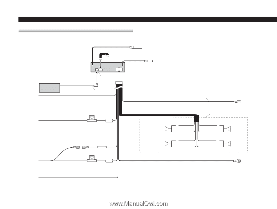
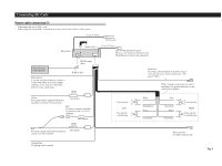
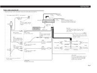
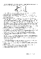
Connecting the Units Power cable connection (1) • When using this unit at 40W × 4ch. • When using this unit at 60W × 4ch and the accessory fuse for the vehicle is 10A or more. 15 cm (5-7/8 in.) Antenna jack This product Refer to Fig. 5. 15 cm (5-7/8 in.) Jack for Wired Remote Control Please see the Instruction Manual for the Wired Remote Control (sold separately). Multi-CD player (sold separately) Yellow/black If you use a cellular telephone, connect it via the Audio Mute lead on the cellular telephone. If not, keep the Audio Mute lead free of any connections. IP-BUS input (Blue) IP-BUS cable Blue/white To system control terminal of the power amp or Auto-antenna relay control terminal (max. 300 mA 12 V DC). With a 2 speaker system, do not connect anything to the speaker leads that are not connected to speakers. Yellow To terminal always supplied with power regardless of ignition switch position. Fuse holder Red To electric terminal controlled by ignition switch (12 V DC) ON/OFF. Fuse resistor Front speaker Left Rear speaker or Subwoofer White + ≠ White/black + Green ≠ Green/black Gray Gray/black Violet Violet/black + Front speaker ≠ Right + Rear speaker or Subwoofer ≠ Red To electric terminal controlled by ignition switch (12 V DC) ON/OFF. Fuse holder Orange/white To lighting switch terminal. Black (ground) To vehicle (metal) body. Fig. 3
-
 1
1 -
2
-
3
-
4
-
5
-
6
-
7
-
8
-
9
-
10
-
11
-
12
-
13
-
14
-
15
-
16
-
17
-
18
-
19
-
20
-
21
-
22
-
23
-
24
-
25
-
26
-
27
-
28
-
29
-
30
-
31
-
32
-
33
-
34
-
35
-
36
-
37
-
38
-
39
-
40
-
41
-
42
-
43
-
44
-
45
-
46
-
47
-
48
-
49
-
50
-
51
-
52
-
53
-
54
-
55
-
56
-
57
-
58
-
59
-
60
-
61
-
62
-
63
-
64
-
65
-
66
-
 67
67 -
 68
68 -
 69
69 -
 70
70 -
 71
71 -
 72
72 -
 73
73 -
 74
74 -
 75
75 -
 76
76 -
 77
77 -
78
-
79
-
80
 |
 |