Pioneer DEH-P80MP Operation Manual - Page 76
DIN Rear-mount, About the fixing screws for the front panel
 |
View all Pioneer DEH-P80MP manuals
Add to My Manuals
Save this manual to your list of manuals |
Page 76 highlights
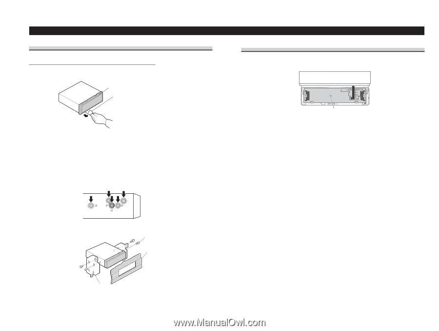
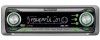
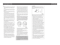
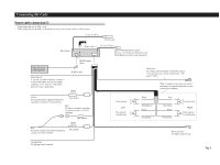
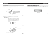
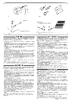
Installation DIN Rear-mount Installation using the screw holes on the side of the unit 1. Remove the frame. (Fig. 11) Frame Insert the release pin into the hole in the bottom of the frame and pull out to remove the frame. (When reattaching the frame, point the side with a groove downwards and attach it.) 2. Fastening the unit to the factory radio mounting bracket. (Fig. 12) (Fig. 13) Select a position where the screw holes of the bracket and the screw holes of the head unit become aligned (are fitted), and tighten the screws at 2 places on each side. Use either truss screws (5 × 8 mm) or flush surface screws (5 × 9 mm), depending on the shape of the screw holes in the bracket. 10 Fig. 11 S11crew Fig. 12 D13ashboard or Console Factory radio mounting br1a2cket Fig. 13 About the fixing screws for the front panel If you do not operate the Detaching and Replacing the Front Panel Function, use the supplied fixing screws and fix the front panel to this unit. Fixing screw Fig. 14
-
 1
1 -
2
-
3
-
4
-
5
-
6
-
7
-
8
-
9
-
10
-
11
-
12
-
13
-
14
-
15
-
16
-
17
-
18
-
19
-
20
-
21
-
22
-
23
-
24
-
25
-
26
-
27
-
28
-
29
-
30
-
31
-
32
-
33
-
34
-
35
-
36
-
37
-
38
-
39
-
40
-
41
-
42
-
43
-
44
-
45
-
46
-
47
-
48
-
49
-
50
-
51
-
52
-
53
-
54
-
55
-
56
-
57
-
58
-
59
-
60
-
61
-
62
-
63
-
64
-
65
-
66
-
67
-
68
-
69
-
70
-
 71
71 -
 72
72 -
 73
73 -
 74
74 -
 75
75 -
 76
76 -
 77
77 -
 78
78 -
 79
79 -
 80
80
 |
 |