Pioneer DEQ-P800 Other Manual
Pioneer DEQ-P800 - Equalizer / Crossover Manual
 |
View all Pioneer DEQ-P800 manuals
Add to My Manuals
Save this manual to your list of manuals |
Pioneer DEQ-P800 manual content summary:
- Pioneer DEQ-P800 | Other Manual - Page 1
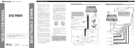
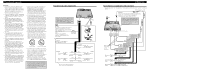
INSTALLATION MANUAL OF OF DEQ-P8000 This product conforms to CEMA cord colors. Le code de couleur des câbles utilisé pour ce produit est conforme à CEMA. Printed in Japan Imprimé au Japon UC N STAR N STAR MANUEL D'INSTALLATION Connecting the Units Note: • This - Pioneer DEQ-P800 | Other Manual - Page 2
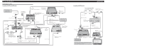
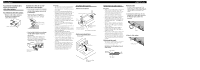
with AV Receiver/DVD player Navigation unit (e.g. AVIC-88DVD) (sold separately) 26 pin cable Guide speaker (e.g. CD-TS37GP) (sold separatly) Yellow 26 pin cable input 3 m (9 ft. 10 in.) Blue Guide speaker output (GUIDE SP OUTPUT) Black 21 pin cable RCA cable (supplied with multi-DVD player - Pioneer DEQ-P800 | Other Manual - Page 3
up properly, and the unit and the system work properly. • Use only the parts included with the unit to ensure proper installation. The use of unauthorized parts can cause malfunctions. • Consult with your nearest dealer if installation requires the drilling of holes or other modifications of the - Pioneer DEQ-P800 | Other Manual - Page 4
haut-parleurs connectés à cet appareil doivent être tels qu'ils puissent supporter une puissance de 50 W, et que leur impédance soit comprise les connecteurs de même couleur comme il convient. • Si cette unité est installée dans un véhicule dont le contacteur d'allumage n'a pas de position ACC ( - Pioneer DEQ-P800 | Other Manual - Page 5
broches Haut-parleur d'assistance (par exemple, CD-TS37GP) (vendu séparément) Jaune Entrée pour câble à 26 broches Sortie pour le haut-parleur d'assistance (GUIDE SP OUT) Noir 3 m Bleu Câble péritel 21 broches Câble à fiches Cinch (RCA) (fourni avec lecteur de DVD à chargeur) Lecteur de DVD - Pioneer DEQ-P800 | Other Manual - Page 6
pluie ou les intempéries. • Avant d'effectuer un perçage requis par l'installation de l'appareil, assurez-vous que vous pouvez le faire sans danger pour les en raison du déplacement du véhicule sur la route. • Si vous choisissez d'installer l'appareil sous un siège avant, veillez à ce qu'il ne gêne
-
 1
1 -
 2
2 -
 3
3 -
 4
4 -
 5
5 -
 6
6
 |
 |
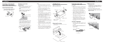
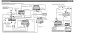
Connecting to a sold separately power amp
This product can be connected to a sold separately power amp using the RCA output jacks.
This product
Blue/white
To system control terminal of the power
amp or Auto-antenna relay control terminal
(max. 300 mA 12 V DC).
+
≠
+
≠
+
≠
+
≠
+
≠
+
≠
Front speaker
Front speaker
Rear speaker
Rear speaker
Center speaker
Subwoofer
System remote control
RCA cables
(sold separately)
Power amp
(sold separately)
Subwoofer output
Rear output
Front output
Center output
Power amp
(sold separately)
Power amp
(sold separately)
Power amp
(sold separately)
When you connect a power amp (sold
separately), be sure to use the blue/white
lead of this unit. If you use the blue/white
lead of the head unit, it causes noises.
40cm
(1 ft. 3-3/4 in.)
Connecting the power cord
Noise filter
Lock tie
Noise filter
Gray/black
White/black
Green
Violet
Left
Right
White
Gray
Green/black
Violet/black
Front speaker
Front speaker
Rear speaker
Rear speaker
This product
Yellow
To terminal always supplied with
power regardless of ignition switch
position.
Fuse holder
Black (ground)
To vehicle (metal) body.
Blue/white
To system control terminal of the power
amp or Auto-antenna relay control terminal
(max. 300 mA 12 V DC).
Do not connect anything to the speaker
leads that are not connected to speakers.
When you connect a power amp (sold
separately), be sure to use the blue/white
lead of this unit. If you use the blue/white
lead of the head unit, it causes noises.
Black
Black/white
Center speaker
+
≠
+
≠
+
≠
+
≠
+
≠
40cm
(1 ft. 3-3/4 in.)
Note:
•
This unit is for vehicles with a 12-volt battery
and negative grounding. Before installing it in a
recreational vehicle, truck, or bus, check the bat-
tery voltage.
•
To avoid shorts in the electrical system, be sure
to disconnect the
·
battery cable before begin-
ning installation.
•
Refer to the owner’s manual for details on con-
necting the power amp and other units, then
make connections correctly.
•
Secure the wiring with cable clamps or adhesive
tape. To protect the wiring, wrap adhesive tape
around them where they lie against metal parts.
•
Route and secure all wiring so it cannot touch
any moving parts, such as the gear shift, hand-
brake and seat rails. Do not route wiring in
places that get hot, such as near the heater outlet.
If the insulation of the wiring melts or gets torn,
there is a danger of the wiring short-circuiting to
the vehicle body.
•
Don’t pass the yellow lead through a hole into
the engine compartment to connect to the battery.
This will damage the lead insulation and cause a
very dangerous short.
•
Do not shorten any leads. If you do, the protec-
tion circuit may fail to work when it should.
•
Never feed power to other equipment by cutting
the insulation of the power supply lead of the
unit and tapping into the lead. The current capac-
ity of the lead will be exceeded, causing over-
heating.
•
When replacing fuse, be sure to use only fuse of
the rating prescribed on the fuse holder.
•
Since a unique BPTL circuit is employed, never
wire so the speaker leads are directly grounded
or the left and right
·
speaker leads are com-
mon.
•
Speakers connected to this unit must be high-
power types with minimum rating of 50 W and
impedance of 4 to 8 ohms. Connecting speakers
with output and/or impedance values other than
those noted here may result in the speakers
catching fire, emitting smoke or becoming dam-
aged.
•
When this product’s source is switched ON, a
control signal is output through the blue/white
lead. Connect to an external power amp’s system
remote control or the car’s Auto-antenna relay
control terminal (max. 300 mA 12 V DC). If the
car features a glass antenna, connect to the anten-
na booster power supply terminal.
•
When an external power amp is being used with
this system, be sure not to connect the blue/white
lead to the amp’s power terminal. Likewise, do
not connect the blue/white lead to the power ter-
minal of the auto-antenna. Such connection could
cause excessive current drain and malfunction.
•
To avoid short-circuiting, cover the disconnected
lead with insulating tape. Especially, insulate the
unused speaker leads without fail. There is a pos-
sibility of short-circuiting if the leads are not
insulated.
•
To prevent incorrect connection, the input side of
the IP-BUS or optical cable connector is blue,
and the output side is black. Connect the connec-
tors of the same colors correctly.
•
If this unit is installed in a vehicle that does not
have an ACC (accessory) position on the ignition
switch, the red lead of the unit should be con-
nected to a terminal coupled with ignition switch
ON/OFF operations. If this is not done, the vehi-
cle battery may be drained when you are away
from the vehicle for several hours.
•
The black lead is ground. Please ground this lead
separately from the ground of high-current prod-
ucts such as power amps.
If you ground the products together and the
ground becomes detached, there is a risk of dam-
age to the products or fire.
•
To ensure proper heat dissipation of this product,
take special care not to block the cooling fan side
of this product.
No ACC position
ACC position
O
N
S
T
A
R
T
O
F
F
A
C
C
O
N
S
T
A
R
T
O
F
F
Connecting the Units
<ENGLISH>
•
Cords for this product and those for other prod-
ucts may be different colors even if they have
the same function. When connecting this prod-
uct to another product, refer to the supplied
manuals of both products and connect cords that
have the same function.
INSTALLATION MANUAL
MANUEL D’INSTALLATION
<KSNNF> <04D00000>
DEQ-P8000
Printed in Japan
Imprimé au Japon
<CRD3878-A> UC
This product conforms to CEMA cord colors.
Le code de couleur des câbles utilisé pour ce produit
est conforme à CEMA.