Pioneer GM-A5702 Owners Manual
Pioneer GM-A5702 Manual
 |
View all Pioneer GM-A5702 manuals
Add to My Manuals
Save this manual to your list of manuals |
Pioneer GM-A5702 manual content summary:
- Pioneer GM-A5702 | Owners Manual - Page 1
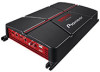
Owner's Manual Mode d'emploi BRIDGEABLE TWO-CHANNEL POWER AMPLIFIER AMPLIFICATEUR DE PUISSANCE PONTABLE À DEUX CANAUX GM-A5702 GM-A3702 English Français - Pioneer GM-A5702 | Owners Manual - Page 2
ELECTRONICS OF CANADA, INC. 340 Ferrier Street, Unit 2, Markham, Ontario L3R 2Z5, Canada TEL: 1-877-283-5901 TEL: 905-479-4411 PIONEER ELECTRONICS DE MÉXICO S.A. de C.V. Blvd.Manuel Ávila Camacho 138, 10 piso Col.Lomas de Chapultepec, México, D.F. 11000 TEL: 52-55-9178-4270 FAX: 52-55- - Pioneer GM-A5702 | Owners Manual - Page 3
SUPPORT DIVISION P.O. Box 1760 Long Beach, CA 90801-1760 800-421-1404 For warranty information please see the Limited Warranty sheet included with this unit. If you experience problems Should this product fail to operate properly, please contact your dealer or nearest authorized Pioneer Service - Pioneer GM-A5702 | Owners Manual - Page 4
or theft. ! Access owner's manuals, spare parts information, service information, and much more. many areas. Before connecting/ installing the amplifier WARNING ! The overheating and smoke, damage to the product and injury, including burns. ! Check the connections of the power supply and speakers - Pioneer GM-A5702 | Owners Manual - Page 5
this unit, smoke, and overheating could result from contact with liquids. The surfaces of the amplifier and any attached speakers may also heat up and illustration below and remove the tag (GMA5702 only). Do not use the parts you have removed (screws etc.) when installing the unit in your vehicle. - Pioneer GM-A5702 | Owners Manual - Page 6
with an RCA equipped Pioneer car stereo, with maximum output of 4 V or more, adjust level to match that of the car stereo output. ! For use with an RCA equipped car stereo with output of 4 V, set to the HIGH position. ! If you hear too much noise when using the speaker input terminals, turn the - Pioneer GM-A5702 | Owners Manual - Page 7
function included to prevent malfunction of the unit and/or speakers due to excessive output, improper use or improper connection. still cuts out periodically. In such cases, please contact the nearest authorized Pioneer Service Station. Gain control of this unit Preout level: 2 V (Standard: - Pioneer GM-A5702 | Owners Manual - Page 8
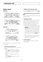
the male terminal to the power terminal via the ignition switch. 9 Speaker output terminals Please see the following section for speaker connection instructions. Refer to Connecting the speakers. a Fuse 30 A × 2 (GM-A5702) / 25 A × 1 (GMA3702) b Fuse (30 A) × 2 c Grommet d Rear side e Front side - Pioneer GM-A5702 | Owners Manual - Page 9
. In addition, refer to the speaker instruction manual for information on the correct connection procedure. ! For any further enquiries, contact your local authorized Pioneer dealer or customer service. About suitable specification of speaker Ensure speakers conform to the following standards - Pioneer GM-A5702 | Owners Manual - Page 10
input: Min. 150 W (GM-A5702) Min. 60 W (GM-A3702) Nominal input: One-channel output Min. 480 W (GM-A5702) Min. 190 W (GM-A3702) 1 Other than subwoofer 1 Speaker (Mono) Speaker channel Two-channel output One-channel output Power MAX input: Min. 300 W (GM-A5702) Min. 170 W (GM-A3702) MAX input - Pioneer GM-A5702 | Owners Manual - Page 11
Speaker output 3 White/black: Left * 4 White: Left + 5 Gray/black: Right * 6 Gray: Right + 7 Speaker input connector To speaker input terminal of this unit. Note If speaker input using the terminal screws, there is a risk of overheating, malfunction and injury, including minor burns. 1 Route - Pioneer GM-A5702 | Owners Manual - Page 12
to wire ends. Use pliers, etc., to crimp lugs to wires. 6 Ground wire 7 System remote control wire Connecting the speaker output terminals 1 Use wire cutters or a utility knife to strip the end of the speaker wires to expose about 10 mm (3/8 in.) of wire and then twist the wire. Twist 1 Lug (sold - Pioneer GM-A5702 | Owners Manual - Page 13
Installation 1 Terminal screws 2 Speaker wires 3 Speaker output terminals Before installing the amplifier WARNING ! To ensure proper installation function may activate to protect the amplifier against overheating due to installation in locations where sufficient heat cannot be dissipated, - Pioneer GM-A5702 | Owners Manual - Page 14
. 3 Install the amplifier with the use of supplied tapping screws (4 mm × 18 mm (1/8 in. × 3/4 in.)). 12 3 4 5 1 Tapping screws (4 mm × 18 mm (1/8 in. × 3/4 in.)) 2 Drill a 2.5 mm (1/8 in.) diameter hole. 3 Floor mat or chassis 4 Hole-to-hole distance: 343 mm (13-1/2 in.) (GM-A5702) / 233 - Pioneer GM-A5702 | Owners Manual - Page 15
Cut off slope 12 dB/oct Bass boost: Frequency 50 Hz Level 0 dB/6 dB/12 dB Gain control: RCA 0.3 V to 6.5 V Speaker 3.0 V to 26 V Maximum input level / impedance: RCA 6.5 V / 22 kW Speaker 26 V / 16 kW CEA2006 Specifications Power output 150 W RMS × 2 Channels (at 14.4 V, 4 W and ≦ 1 % THD - Pioneer GM-A5702 | Owners Manual - Page 16
Additional information Maximum input level / impedance: RCA 6.5 V / 22 kW Speaker 26 V / 16 kW CEA2006 Specifications Power output 60 W RMS × 2 Channels (at 14.4 V, 4 W and ≦ 1 % THD +N) S/N ratio 78 dBA (reference: 1 W into 4 W) Notes ! Specifications and the design are subject to modifications - Pioneer GM-A5702 | Owners Manual - Page 17
le distributeur ou le service d'entretien agréé par Pioneer le plus proche. Service après-vente des produits Pioneer Veuillez contacter le revendeur pris contact au préalable. ÉTATS-UNIS ET CANADA Pioneer Electronics (USA) Inc. CUSTOMER SUPPORT DIVISION P.O. Box 1760 Long Beach, CA 90801-1760 800 - Pioneer GM-A5702 | Owners Manual - Page 18
Avant de commencer Visitez notre site Web http://www.pioneerelectronics.com au Canada http://www.pioneerelectronics.ca ! Informez-vous sur les mises à jour disponi- bles pour votre produit (telles que les mises à jour du firmware). ! Enregistrez votre produit afin de recevoir des notifications - Pioneer GM-A5702 | Owners Manual - Page 19
borne négative * de la batterie préalablement, de manière à éviter tout risque de choc électrique ou de court-circuit lors de l'installation. ! N'essayez pas de démontez ou de modifiez cet appareil. Ceci pourrait provoquer un incendie, une électrocution ou tout autre dysfonctionnement. PRÉCAUTION - Pioneer GM-A5702 | Owners Manual - Page 20
indicateur de mise sous tension s'éteint et l'amplificateur se met hors service. Important (Numéro de série) Le numéro de l'installation de l'appareil dans votre véhicule. Description de l'appareil GM-A5702 Face avant Face arrière GM- basse fréquence. ! Lorsque le haut-parleur pleine gamme est connecté - Pioneer GM-A5702 | Owners Manual - Page 21
LPF est réglé sur ON. 3 Commutateur BASS BOOST (commande du niveau d'accentuation des graves) Vous Pour l'utilisation avec un système stéréo de véhicule Pioneer équipé d'une sortie RCA, dont la sortie maximale au niveau de sortie maximal de la sortie préamp de l'appareil central de manière à ce que - Pioneer GM-A5702 | Owners Manual - Page 22
RCA (vendu sépa- rément) 6 Borne d'entrée des haut-parleurs (utilisez un connecteur fourni) Veuillez vous reporter à la section suivante pour les instructions de connexion des hautparleurs. Reportez-vous à Connexions lors de l'utilisation du fil d'entrée des haut-parleurs. 7 Jack d'entrée RCA Fr - Pioneer GM-A5702 | Owners Manual - Page 23
de sortie des haut-parleurs Veuillez vous reporter à la section suivante pour les instructions de connexion des hautparleurs. Reportez-vous à Connexion des hautparleurs. a Fusible 30 A × 2 (GM-A5702) / 25 A × 1 (GMA3702) b Fusible (30 A) × 2 c Rondelle d Face arrière e Face avant Avant de connecter - Pioneer GM-A5702 | Owners Manual - Page 24
et provoquer ainsi des brûlures mineures. Pour installer ou utiliser un mode ponté de manière appropri te, veuillez contacter le service clientèle ou votre revendeur Pioneer agréé local. À (GM-A5702) 170 W min. (GM-A3702) Sortie un canal Entrée max.: 1000 W min. (GM-A5702) 500 W min. (GM-A3702 - Pioneer GM-A5702 | Owners Manual - Page 25
Connexion des appareils Sortie deux canaux (stéréo) 1 2 1 Haut-parleur (gauche) 2 Haut-parleur (droit) Sortie un canal 1 1 Haut-parleur (mono) Connexions lors de l'utilisation du fil d'entrée des haut-parleurs Connectez les fils de sortie des haut-parleurs du système stéréo du véhicule à l' - Pioneer GM-A5702 | Owners Manual - Page 26
Connexion des appareils Connexion de la borne d'alimentation L'utilisation d'un fil de batterie rouge spécial et d'un fil de terre RD-223 (vendus séparément) est recommandée. Connectez le fil de la batterie directement sur la borne positive + de la batterie du véhicule et le fil de terre sur la - Pioneer GM-A5702 | Owners Manual - Page 27
Connexion des appareils 1 Borne de la télécommande du système 2 Borne de masse 3 Borne d'alimentation 4 Vis de la borne 5 Fil de la batterie 6 Fil de terre 7 Fil de la télécommande du système Connexion des bornes de sortie des haut-parleurs 1 Utilisez une pince coupante ou un couteau à lame ré - Pioneer GM-A5702 | Owners Manual - Page 28
cela pourrait entraîner un court-circuit. ! Lorsque vous percez pour installer l'amplificateur, vérifiez toujours qu'il n'y a aucune pièce derrière échéant, l'amplificateur réduit la puissance de sortie ou se met hors service jusqu'à ce qu'il se soit refroidi et atteigne une certaine température. - Pioneer GM-A5702 | Owners Manual - Page 29
tournevis de manière créer une empreinte de l'emplacement des trous d'installation. 2 Percez des trous de 2,5 mm de diamètre au niveau des mm (GM- A5702) / 233 mm (GM-A3702) 5 Distance entre les trous : 195 mm (GM- A5702) / 160 mm (GM-A3702) Caractéristiques techniques GM-A5702 Tension d' - Pioneer GM-A5702 | Owners Manual - Page 30
et ≦ 1 % DHT+N) Rapport S/B 75 dBA (référence : 1 W sur 4 W) GM-A3702 Tension d'alimentation ......... 14,4 V CC (10,8 V à 15,1 V acceptable) V Niveau d'entrée maximal/impédance : RCA 6,5 V / 22 kW Puissance de sortie 60 W RMS x 2 Canaux (à 14,4 V, 4 W et ≦ 1 % DHT+N) Rapport S/B 78 dBA (réfé - Pioneer GM-A5702 | Owners Manual - Page 31
- Pioneer GM-A5702 | Owners Manual - Page 32
-
 1
1 -
 2
2 -
 3
3 -
 4
4 -
 5
5 -
 6
6 -
 7
7 -
8
-
9
-
10
-
11
-
12
-
13
-
14
-
15
-
16
-
17
-
18
-
19
-
20
-
21
-
22
-
23
-
24
-
25
-
26
-
27
-
28
-
29
-
30
-
31
-
32
 |
 |

English
Français
BRIDGEABLE TWO-CHANNEL POWER AMPLIFIER
AMPLIFICATEUR DE PUISSANCE PONTABLE À DEUX CANAUX
GM-A5702
GM-A3702
Owner’s Manual
Mode d’emploi