Pioneer GM-X1024 Service Manual
Pioneer GM-X1024 Manual
 |
View all Pioneer GM-X1024 manuals
Add to My Manuals
Save this manual to your list of manuals |
Pioneer GM-X1024 manual content summary:
- Pioneer GM-X1024 | Service Manual - Page 1
GM-X1024/X1R/UC Service Manual ORDER NO. CRT2191 BRIDGEABL FOUR-CHANNEL POWER AMPLIFIER GM-X1024 X1R/UC GM-X924 X1R/UC,EW,ES CONTENTS 1. SAFETY INFORMATION 2 2. EXPLODED VIEWS AND PARTS LIST 2 3. SCHEMATIC DIAGRAM 8 4. PCB CONNECTION DIAGRAM 14 5. ELECTRICAL PARTS LIST 19 6. ADJUSTMENT 25 - Pioneer GM-X1024 | Service Manual - Page 2
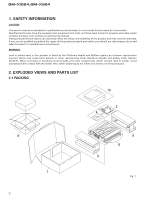
GM-X1024,GM-X924 1. SAFETY INFORMATION CAUTION This service manual is intended for qualified service technicians; it is not meant for the casual do-it-yourselfer. Qualified technicians have the necessary test equipment and tools, and have been trained to - Pioneer GM-X1024 | Service Manual - Page 3
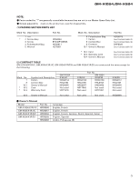
Not used HRY1087 X1R/ES HHG0157 HHL0157 HRD0058 Not used Not used 10-4 Owner's Manual Not used Not used Not used HRD0068 - Owner's Manual Model GM-X1024/X1R/UC GM-X924/X1R/UC GM-X924/X1R/EW GM-X924/X1R/ES Part No. HRD0056 HRD0057 HRD0059 HRD0058 HRD0068 Language English, French English - Pioneer GM-X1024 | Service Manual - Page 4
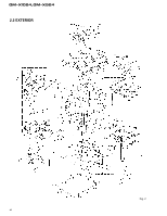
GM-X1024,GM-X924 2.2 EXTERIOR Fig. 2 4 - Pioneer GM-X1024 | Service Manual - Page 5
GM-X1024,GM-X924 (1) EXTERIOR SECTION PARTS LIST Mark No. Description 1 Screw(M3×25) 2 10 Separator HBA0011 HBA0012 HBF0005 HNB0036 HNM0046 11 Heat Sink 12 Window 13 Lighting Conductor 14 Amp Unit 15 Screw See Contrast table (2) HNS0053 HNV0012 See Contrast table (2) BMS30P060FZK 16 Screw 17 - Pioneer GM-X1024 | Service Manual - Page 6
the following: Mark No. 11 14 39 64 65 Symbol and Description Heat Sink Amp Unit Network Unit Plate Unit Sheet Unit GM-X1024 X1R/UC HNR0073 HWH0066 HWG0008 HXA0262 HXA0264 Part No. GM-X924 X1R/UC X1R/EW HNR0093 HNR0093 HWH0067 HWH0064 HWG0009 HWG0006 HXA0112 HXA0112 HXA0116 HXA0116 - Pioneer GM-X1024 | Service Manual - Page 7
GM-X1024,GM-X924 7 - Pioneer GM-X1024 | Service Manual - Page 8
1 2 3 4 GM-X1024,GM-X924 3. SCHEMATIC DIAGRAM A 3.1 OVERALL CONNECTION DIAGRAM(GUIDE PAGE) Note: When ordering service parts, be sure to refer to "EXPLODED VIEWS AND PARTS LIST" or "ELECTRICAL PARTS LIST". A-a Large size A-a A-b SCH diagram B -10dBm -7.7dBm -10.2dBm HPF LPF VR501: - Pioneer GM-X1024 | Service Manual - Page 9
5 6 7 8 GM-X1024,GM-X924 A A-b POWER STAGE A OVER CURRENT DETECTOR B 20.4dBm E F C THERMO DETECTOR / PROTECTOR OVER VOLTAGE DETECTOR / PROTECTOR MUTE CONTROL REGULATOR CONTROL 0.1V 3.2V 0.3V 5V 0V 0.2V 0V 0V 0.2V 14.4V 14.2V 10.7V 14.4V 14.4V 5 6 D Fig. 3 AEF 9 7 8 - Pioneer GM-X1024 | Service Manual - Page 10
A B C D 1 GM-X1024,GM-X924 10 A-a B C D 1 -10dBm -7.7dBm -10.2dBm HPF LPF VR501:FREQUENCY S501:LPF/HPF OFF A-a A-b -14.4dBm 2 2 3 3 2CH/4CH 2CH 4CH ISOLATOR HPF VR501:FREQUENCY OFF S501:LPF/HPF LPF VR551:FREQUENCY S551:LPF/HPF OFF VR551:FREQUENCY OFF S551:LPF/HPF 4 4 - Pioneer GM-X1024 | Service Manual - Page 11
+29.0V RECTIFICATION DC-AC INVERTER -15V REGULATOR SWITCHING CONTROL 3.9V 3.9V 14.4V 5V 5V 2.4V 2.4V 14.4V 0V 3.8V 1.8V 2.2V 0V GM-X924/X1R/EW, GM-X924/X1R/ES BFC H L 6.5V D903,D904:NSPWF50S(AQ) A-a A-b 7 7 GM-X1024,GM-X924 A-a B D 11 8 8 Fig. 4 A B C D - Pioneer GM-X1024 | Service Manual - Page 12
4 3 2 1 12 A-b E F -14.4dBm D C B POWER STAGE OVER CURRENT DETECTOR A-a A-b 20.4dBm A GM-X1024,GM-X924 4 3 2 1 - Pioneer GM-X1024 | Service Manual - Page 13
8 7 6 5 A-b F 13 Fig. 5 D THERMO DETECTOR / PROTECTOR OVER VOLTAGE DETECTOR / PROTECTOR MUTE CONTROL REGULATOR CONTROL 0.1V 3.2V 0.3V 5V 0V 0.2V 0V 0V 0.2V 14.4V 14.2V 10.7V 14.4V 14.4V (AQ) C B A A-a A-b GM-X1024,GM-X924 8 7 6 5 - Pioneer GM-X1024 | Service Manual - Page 14
1 2 GM-X1024,GM-X924 3 4 NOTE FOR PCB DIAGRAMS 1. The parts mounted on this PCB include all necessary parts for several destination. 4. PCB CONNECTION DIAGRAM For further information for respective destinations, be sure to check with the schematic diagram. A 4.1 AMP UNIT A AMP UNIT B - Pioneer GM-X1024 | Service Manual - Page 15
5 6 2. Viewpoint of PCB diagrams Connector Capacitor SIDE A P.C.Board Chip Part SIDE B 7 8 GM-X1024,GM-X924 SIDE A A BFC FU901 FU902 BACKUP B GND SYSTEM CONTROL AR+ AR- SPEAKER OUTPUT AL- B C AL+ BR+ BR- SPEAKER OUTPUT BL- A D BL+ Fig. 6 A 15 5 6 7 8 - Pioneer GM-X1024 | Service Manual - Page 16
1 2 GM-X1024,GM-X924 4.2 ISO PCB A 3 4 SIDE A D CN551 A CN852 B C A CN853 C CN501 ISO PCB B D B 16 1 2 Fig. 7 3 4 - Pioneer GM-X1024 | Service Manual - Page 17
1 2 3 4 GM-X1024,GM-X924 4.3 A LPF/HPF PCB C A LPF/HPF PCB S501 LPF/HPF FREQUENCY GAIN S501 1 6 2 7 3 8 4 9 5 10 A SIDE A B CN854 A CN503 B Fig. 8 4.4 B LPF/HPF PCB D B LPF/HPF PCB 10 9 8 7 6 - Pioneer GM-X1024 | Service Manual - Page 18
1 2 3 4 GM-X1024,GM-X924 4.5 A P.A. PCB A E A P.A. PCB SIDE A B 4.6 B P.A. PCB F B P.A. PCB C A CN103 Fig. 10 SIDE A D E F 18 1 2 A CN303 Fig. 11 3 4 - Pioneer GM-X1024 | Service Manual - Page 19
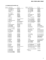
Consists of ISO PCB A LPF/HPF PCB B LPF/HPF PCB A P.A.PCB B P.A.PCB B C D E F Unit Number : HWG0008 (GM-X1024/X1R/UC) Unit Number : HWG0009 (GM-X924/X1R/UC) Unit Number : HWG0006 (GM-X924/X1R/EW) Unit Number : HWG0007 (GM-X924/X1R/ES) Unit Name : Network Unit MISCELLANEOUS IC 501 IC IC 502 IC IC - Pioneer GM-X1024 | Service Manual - Page 20
GM-X1024,GM-X924 =====Circuit Symbol and No.===Part Name R 406 R 407 R 409 R 410 R 411 R 412 R 501 R 502 R 503 R 504 R 505 R 506 R 507 R 508 R 509 R 510 R 511 R 512 R - Pioneer GM-X1024 | Service Manual - Page 21
C 884 C 885 C 886 C 887 CQMA472J50 CCPUSL470J50 CCPUSL470J50 CCPUSL470J50 A Unit Number : HWH0066(GM-X1024/X1R/UC) Unit Number : HWH0067(GM-X924/X1R/UC) Unit Number : HWH0064(GM-X924/X1R/EW) Unit Number : HWH0065(GM-X924/X1R/ES) Unit Name : Amp Unit MISCELLANEOUS IC 505 IC IC 506 IC IC 651 IC IC - Pioneer GM-X1024 | Service Manual - Page 22
GM-X1024,GM-X924 =====Circuit Symbol and No.===Part Name D 405 Diode D 611 Diode D 621 Diode D 631 Diode D 641 Diode D 651 Diode D 652 Diode D 653 Diode D 654 Diode D - Pioneer GM-X1024 | Service Manual - Page 23
GM-X1024,GM-X924 =====Circuit Symbol and No.===Part Name R 663 R 664 R 665 R 666 R 667 R 668 R 669 R 670 R 671 R 672 R 673 R 674 R 675 R 691 R 692 R 801 R 802 R 803 R - Pioneer GM-X1024 | Service Manual - Page 24
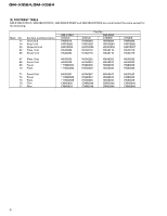
CQPA102J2A CFTLA104J50 CFTLA104J50 CONTRAST TABLE of AMP UNIT GM-X1024/X1R/UC, GM-X924/X1R/UC, GM-X924/X1R/EW and GM-X924/X1R/ES are constructed the same except for the following: Part No. Symbol and Description GM-X1024/X1R/UC GM-X924/X1R/UC GM-X924/X1R/EW GM-X924/X1R/ES S901 Switch Not - Pioneer GM-X1024 | Service Manual - Page 25
GM-X1024,GM 20±6mV mV Meter(2) : +29±3V mV Meter(3) : -29±3V - Connection Diagram +14.4V DC Regulated Power Supply 4Ω (2W) SPEAKER A OUTPUT 4Ω (2W) Meter (1) Q115 Q116 E C VR101 E C mV Meter + (3) mV Meter + (2) AMP UNIT GND BR GND 1kΩ VR401 E E VR301 E E Q415 Q416 mV Meter (1) - Pioneer GM-X1024 | Service Manual - Page 26
GM-X1024,GM-X924 7. GENERAL INFORMATION 7.1 IC PA2027A VCC 1 Transient voltage detector Stby 2 Bandgap DET1 3 DET2 4 + - Circuit motion:on zz 50µA zz+- 16 IN1 2V zz+- 15 IN2 - Pioneer GM-X1024 | Service Manual - Page 27
GM-X1024,GM-X924 7.2 DISASSEMBLY A Panel Unit A A BB BB A B C B A A A BC Panel Unit Sink Some silicone glue has been applied between the Heat Sink and the Heat Sink(Sub). therefore, to remove the Amp Unit from the Heat Sink. 1. Remove two screws D. 2. Remove A LPF/HPF PCB and B LPF/HPF PCB - Pioneer GM-X1024 | Service Manual - Page 28
GM-X1024,GM-X924 7.3 BLOCK DIAGRAM Fig. 15 28 - Pioneer GM-X1024 | Service Manual - Page 29
8. OPERATIONS AND SPECIFICATIONS 8.1 OPERATIONS - GM-X1024/X1R/UC Setting the Unit Gain Control Adjusting the gain controls A and B will help match the output of the car stereo to the Pioneer amplifier. Normally, set the switch to the "NORMAL" position. If the output is low, even when the volume - Pioneer GM-X1024 | Service Manual - Page 30
: Min. 150 W Max. input: Min. 300 W Connection Diagram Fuse (30 A) Grommet Fuse (30 A) Special red battery wire [RD-223] (sold separately). After making all other connections at the amplifier, connect the battery wire terminal of the amplifier to the positive (+) terminal of the battery. Ground - Pioneer GM-X1024 | Service Manual - Page 31
GM-X924/X1R/EW Setting the Unit Gain Control Adjusting the gain controls A and B will help match the output of the car stereo to the Pioneer amplifier. your car stereo, change the BFC switch using a small screwdriver. GM-X1024,GM-X924 RCA Input Select Switch For two-channel input, slide this - Pioneer GM-X1024 | Service Manual - Page 32
: Min. 150 W Max. input: Min. 300 W Connection Diagram Fuse (30 A) Grommet Fuse (30 A) Special red battery wire [RD-223] (sold separately). After making all other connections at the amplifier, connect the battery wire terminal of the amplifier to the positive (+) terminal of the battery. Ground - Pioneer GM-X1024 | Service Manual - Page 33
255 (W) × 61 (H) × 310 (D) mm [10 (W) × 2-3/8 (H) × 12-1/4 (D) in.] Weight ...4.1 kg (9.0 lbs.) (Leads for wiring not included) Maximum power output ...130 W × 4 / 300 W × 2 (EIAJ) Continuous power output 65 W × 4 (at 14.4 V, total current drawn by multiple power amplifiers. GM-X1024,GM-X924 33
-
 1
1 -
 2
2 -
 3
3 -
 4
4 -
 5
5 -
 6
6 -
 7
7 -
8
-
9
-
10
-
11
-
12
-
13
-
14
-
15
-
16
-
17
-
18
-
19
-
20
-
21
-
22
-
23
-
24
-
25
-
26
-
27
-
28
-
29
-
30
-
31
-
32
-
33
 |
 |

GM-X1024/X1R/UC
BRIDGEABL FOUR-CHANNEL POWER AMPLIFIER
GM-X1024
X1R/UC
S
e
r
v
i
c
e
M
a
nu
a
l
GM-X924
X1R/UC,EW,ES
PIONEER ELECTRONIC CORPORATION
4-1, Meguro 1-Chome, Meguro-ku, Tokyo 153-8654, Japan
PIONEER ELECTRONICS SERVICE INC.
P.O.Box 1760, Long Beach, CA 90801-1760 U.S.A.
PIONEER ELECTRONIC [EUROPE] N.V.
Haven 1087 Keetberglaan 1, 9120 Melsele, Belgium
PIONEER ELECTRONICS ASIACENTRE PTE.LTD.
501 Orchard Road, #10-00, Lane Wheelock Place, Singapore 23880
C
PIONEER ELECTRONIC CORPORATION 1998
ORDER NO.
CRT2191
CONTENTS
1. SAFETY INFORMATION
............................................
2
2. EXPLODED VIEWS AND PARTS LIST
.......................
2
3. SCHEMATIC DIAGRAM
.............................................
8
4. PCB CONNECTION DIAGRAM
................................
14
5. ELECTRICAL PARTS LIST
........................................
19
6. ADJUSTMENT
..........................................................
25
7. GENERAL INFORMATION
.......................................
26
7.1 IC
........................................................................
26
7.2 DISASSEMBLY
...................................................
27
7.3 BLOCK DIAGRAM
..............................................
28
8. OPERATIONS AND SPECIFICATIONS
.....................
29
K-FED. MAR. 1998 Printed in Japan