Pioneer IS-21MD Service Manual
Pioneer IS-21MD Manual
 |
View all Pioneer IS-21MD manuals
Add to My Manuals
Save this manual to your list of manuals |
Pioneer IS-21MD manual content summary:
- Pioneer IS-21MD | Service Manual - Page 1
connect it to the prescribed system component(s), otherwise damage may result. Component CD MD TUNER CD TUNER DECK STEREO POWER AMPLIFIER SPEAKER SYSTEM System IS-21MD IS-21T XC-IS21MD --- --- XC-IS21T M-IS21 M-IS21 S-IS21 S-IS21 Service Manual Remarks RRV2124 RRV2123 RRV2129 RRV2128 - Pioneer IS-21MD | Service Manual - Page 2
or other hazards. Product Safety is continuously under review and new instructions are issued from time to time. For the latest information, always consult the current PIONEER Service Manual. A subscription to, or additional copies of, PIONEER Service Manual may be obtained at a nominal charge from - Pioneer IS-21MD | Service Manual - Page 3
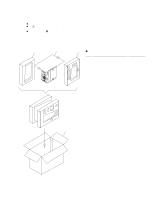
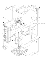
M-IS21 2. EXPLODED VIEWS AND PARTS LIST NOTES: Parts marked by "NSP" are generally unavailable because they are not in our Master Spare Parts List. The mark found on some component parts indicates the importance of the safety factor of the part. Therefore, when replacing, be sure to use parts of - Pioneer IS-21MD | Service Manual - Page 4
M-IS21 2.2 EXTERIOR 36 28 32 26 32 36 36 34 32 8 36 32 19 20 11 15 36 7 36 32 14 16 25 4 31 29 27 6 9 4 32 5 37 38 10 C11 C12 1 32 36 28 32 13 32 - Pioneer IS-21MD | Service Manual - Page 5
M-IS21 Caution when disassemble. Even if the power supply code is pulled out from the outlet, neither C11 nor C12 of AF ASSY are discharged. Please discharge C11 and C12 of AF ASSY by the resistor of 100 Ω or more before removing AF ASSY or POWER SUPPLY ASSY. There is a possibility to destroy the - Pioneer IS-21MD | Service Manual - Page 6
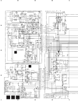
1 2 3 4 M-IS21 3. SCHEMATIC DIAGRAM 3.1 AF, AMP, POWER SUPPLY, PRIMARY, SECONDARY, HP, METER and METER CONNECT ASSYS A B B AMP ASSY (AWU7340) C C POWER SUPPLY ASSY (AWU7344) D 6ABC 1 2 3 4 - Pioneer IS-21MD | Service Manual - Page 7
FIRE, REPLACE ONLY WITH SAME TYPE NO. 4911.25, MFD BY LITTELFUSE INK. FOR IC33 (AEK7048). : AUDIO SIGNAL ROUTE 7 8 M-IS21 Note : When ordering service parts, be sure to refer to "EXPLODED VIEWS and PARTS LIST" or "PCB PARTS LIST" A B F HP ASSY (AWU7351) G METER ASSY (AWU7353) H METER CONNECT - Pioneer IS-21MD | Service Manual - Page 8
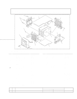
1 2 3 4 M-IS21 4. PCB CONNECTION DIAGRAM A NOTE FOR PCB DIAGRAMS: 1. Part numbers in PCB diagrams match those in the schematic 3. The parts mounted on this PCB include all necessary parts diagrams. for several destination. 2. A comparison between the main parts of PCB and schematic For - Pioneer IS-21MD | Service Manual - Page 9
1 2 3 4.2 HP, METER and METER CONNECT ASSYS H METER CONNECT ASSY G METER ASSY 4 M-IS21 A F HP ASSY A CN3105 B A CN3104 (ANP7300-C) H METER CONNECT ASSY 1 POWER METER G METER ASSY Q5604 IC5601 Q5601 Q5602 Q5603 SIDE A F C HP ASSY D (ANP7300-C) SIDE B FGH9 2 3 4 - Pioneer IS-21MD | Service Manual - Page 10
1 2 3 4 M-IS21 4.3 AF ASSY A IC3302 B CN3006 B CN3003 F J3004 XC-IS21MD or XC-IS21T C B CN3002 G J3005 IC82 IC81 Q81 CA AF ASSY E 3001 L BROWN D D N BLUE AC IN NEUTRAL LIVE D SIDE A (ANP7300-C) A 10 1 2 3 4 - Pioneer IS-21MD | Service Manual - Page 11
1 2 A AF ASSY SIDE B (ANP7300-C) 3 4 M-IS21 Q3313 Q3602 A Q85 Q3603 Q3601 Q3607 Q3608 Q3606 Q3605 B Q3621 Q82 C D A 11 1 2 3 4 - Pioneer IS-21MD | Service Manual - Page 12
1 2 3 M-IS21 4.4 AMP and POWER SUPPLY ASSYS C POWER A SUPPLY ASSY B B C AMP ASSY A CN3102 A CN3106 A CN3103 4 IC24 IC23 Q33 Q43 Q42 Q32 Q3651 Q3654 IC33 IC42 Q3502 Q3501 IC3301 D SIDE A (ANP7300-C) Q3352 Q3351 B C 12 1 2 3 4 - Pioneer IS-21MD | Service Manual - Page 13
1 2 3 4 M-IS21 C POWER SUPPLY A IC32 ASSY Q31 Q41 Q3652 Q3653 B Q3311 Q3312 Q3503 IC3502 IC3501 B AMP C ASSY Q3353 Q3354 D SIDE B (ANP7300-C) B C 13 1 2 3 4 - Pioneer IS-21MD | Service Manual - Page 14
CEATR10M50 CKSQYF104Z50 CQMA102K2E RESISTORS R3333, R3334 R82 R3601, R3602 Other Resistors RD1/4LMF101J RD1/4PU220J RS3LMFR22J RS1/10S J OTHERS 3101 12P CABLE HOLDER CN3105 4PJUMPER CONNECTOR JA3333 2P PIN JACK CN3332 10P SOCKET CN3103 5P SOCKET 51048-1200 52151-0410 AKB7043 AKP7048 AKP7051 - Pioneer IS-21MD | Service Manual - Page 15
RD1/2PM330J RS1/10S J AKM7012 D PRIMARY ASSY PRIMARY assembly has no service part. E SECONDARY ASSY SEMICONDUCTORS IC41 PROTECTOR(3.5A) IC31 PROTECTOR(4A) , IC22 PROTECTOR(5A) IC11, IC12 PROTECTOR(7A) OTHERS 3001 12P CABLE HOLDER F HP ASSY COILS AND FILTERS L3992-L3994 CHIP BEADS CAPACITORS - Pioneer IS-21MD | Service Manual - Page 16
10S J 51048-0300 51048-0400 D20PYY0410E H METER CONNECT ASSY SEMICONDUCTORS D5603 D5602 MTZJ5.6C NSPBF50S-8451 RESISTORS All Resistors RS1/10S J OTHERS 5602 J5601 3P CABLE HOLDER 3P JUMPER WIRE 51048-0300 D20PYY0315E 6. ADJUSTMENT There is no information to be shown in this chapter. 16 - Pioneer IS-21MD | Service Manual - Page 17
(JA3333), and the output is confirmed with speaker terminal (CN3331). Note : If the music signal is input directly to input terminal (JA3333) with CD PLAYER etc. , the output becomes a large volume because there are 40dB GAIN of the amplifier. A AF ASSY CONNECT A POINT (GND) (FOUR PLACES) INPUT - Pioneer IS-21MD | Service Manual - Page 18
M-IS21 8. PANEL FACILITIES AND SPECIFICATIONS ¶ PANEL FACILITIES ¶ SPECIFICATIONS 7 Amplifier Section Continuous Power (RMS 100 W + 100 Wz (1 kHz, THD 10%, 6 Ω) Continuous Power (DIN 65 W + 65 W (1 kHz, THD 1%, 6 Ω) Music Power (DIN 150 W + 150 W (1 kHz, THD 1%, 6 Ω) ¶ Above specifications
-
 1
1 -
 2
2 -
 3
3 -
 4
4 -
 5
5 -
 6
6 -
 7
7 -
8
-
9
-
10
-
11
-
12
-
13
-
14
-
15
-
16
-
17
-
18
 |
 |

ORDER NO.
PIONEER ELECTRONIC CORPORATION
4-1, Meguro 1-Chome, Meguro-ku, Tokyo 153-8654, Japan
PIONEER ELECTRONICS SERVICE, INC.
P.O. Box 1760, Long Beach, CA 90801-1760, U.S.A.
PIONEER ELECTRONIC (EUROPE) N.V.
Haven 1087, Keetberglaan 1, 9120 Melsele, Belgium
PIONEER ELECTRONICS ASIACENTRE PTE. LTD.
253 Alexandra Road, #04-01, Singapore 159936
PIONEER ELECTRONIC CORPORATION 1999
RRV2129
STEREO POWER AMPLIFIER
M-IS21
1. SAFETY INFORMATION
......................................
2
2. EXPLODED VIEWS AND PARTS LIST
................
3
3. SCHEMATIC DIAGRAM
.......................................
6
4. PCB CONNECTION DIAGRAM
............................
8
5. PCB PARTS LIST
...............................................
14
6. ADJUSTMENT
....................................................
16
CONTENTS
7. GENERAL INFORMATION
................................
17
7.1
SINGLE OPERATION METHOD
.................
17
8. PANEL FACILITIES AND SPECIFICATIONS
....
18
THIS MANUAL IS APPLICABLE TO THE FOLLOWING MODEL(S) AND TYPE(S).
T – ZZK
APR. 1999 Printed
in Japan
Type
Model
Power Requirement
Remarks
M-IS21
MYXJ
AC220-230V
NVXJ
AC230V
This product is a component of a system.
For the accessories, instruction manuals etc., refer to the service manuals RRV2124 for
XC-IS21MD and RRV2123 for XC-IS21T.
This product does not function properly when independent; to avoid malfunctions, be
sure to connect it to the prescribed system component(s), otherwise damage may
result.
Component
System
Service Manual
Remarks
IS-21MD
IS-21T
CD MD TUNER
XC-IS21MD
–––
RRV2124
CD TUNER DECK
–––
XC-IS21T
RRV2123
STEREO POWER AMPLIFIER
M-IS21
M-IS21
RRV2129
This Service Manual
SPEAKER SYSTEM
S-IS21
S-IS21
RRV2128