Pioneer KEH-P2030 Service Manual
Pioneer KEH-P2030 Manual
 |
View all Pioneer KEH-P2030 manuals
Add to My Manuals
Save this manual to your list of manuals |
Pioneer KEH-P2030 manual content summary:
- Pioneer KEH-P2030 | Service Manual - Page 1
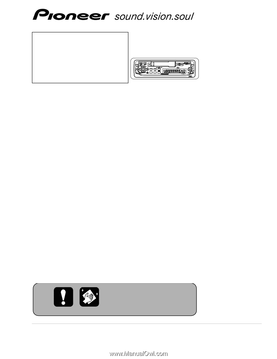
BOOSTER BAND KEH-P2030/XM/UC MULTI-CD CONTROL HIGH POWER CASSETTE PLAYER WITH FM/AM TUNER KEH-P2030 XM/UC KEH-P2035 XM/ES ORDER NO. CRT2980 - This service manual does not describe the CD test mode. For the operations in the CD test mode, refer to the CD player's Service manual. CONTENTS SAFETY - Pioneer KEH-P2030 | Service Manual - Page 2
glue may lead to failures or troubles in the product. By following the instructions in this manual, be sure to apply the prescribed grease or glue to proper portions by the appropriate amount.For replacement parts or tools, the prescribed ones should be used. F 2 KEH-P2030/XM/UC 1 2 3 4 - Pioneer KEH-P2030 | Service Manual - Page 3
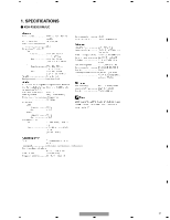
5 6 7 1. SPECIFICATIONS - KEH-P2030/XM/UC Backup current Less than 3 mA 4.76 cm/sec. (+0.14cm/sec., -0.05cm/sec.) KEH-P2030/XM/UC 5 6 7 8 A B C D E F 3 8 - Pioneer KEH-P2030 | Service Manual - Page 4
1 2 3 4 A - KEH-P2035/XM/ES B Backup current Less than 3 mA C D 4.76 cm/sec. (+0.14cm/sec., -0.05cm/sec.) E F 4 KEH-P2030/XM/UC 1 2 3 4 - Pioneer KEH-P2030 | Service Manual - Page 5
5 6 7 8 A B C D E F KEH-P2030/XM/UC 5 5 6 7 8 - Pioneer KEH-P2030 | Service Manual - Page 6
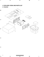
1 2 3 A 2. EXPLODED VIEWS AND PARTS LIST 2.1 PACKING 5 14 15 12 10 11 6 8 B 9 13 7 16 3 4 1 C 4 17 18 D 2 E F 6 KEH-P2030/XM/UC 1 2 3 4 - Pioneer KEH-P2030 | Service Manual - Page 7
15 Screw 16 Protector 17 Protector 18 Carton Part No. TRZ50P080FMC CZH5592 CZH5591 CZH5595 D E - Owner's Manual, Installation Manual Model Part No. KEH-P2030/XM/UC CZR2953 CZR2954 KEH-P2035/XM/ES CZR2955 CZR2956 Language English, French, Spanish English, French, Spanish English, Spanish - Pioneer KEH-P2030 | Service Manual - Page 8
1 2 3 4 2.2 EXTERIOR A B C D E F 8 KEH-P2030/XM/UC 1 2 3 4 - Pioneer KEH-P2030 | Service Manual - Page 9
) 57 Spring 58 Spring CZA5565 CZA5564 CZA5563 CZB2976 CZB2977 59 Cover CZN6753 C 60 Screw IMS20P030FZK 61 Screw ISS26P055FUC 62 Transistor(Q604) 2SD2396 63 IC(IC500)(KEH-P2030) TDA7384 IC(IC500)(KEH-P2035) TA8277H 64 Panel CNS7399 D E F KEH-P2030/XM/UC 9 5 6 7 8 - Pioneer KEH-P2030 | Service Manual - Page 10
1 2 3 4 A 2.3 CASSETTE MECHANISM B C D E F 10 KEH-P2030/XM/UC 1 2 3 4 - Pioneer KEH-P2030 | Service Manual - Page 11
5 6 7 8 - CASSETTE MECHANISM SECTION PARTS LIST Mark No. Description 0036-4010 10138-2005-3 1-0138-1006 11 Pinch Arm (F) Assy 12 Spring 13 Screw 14 Tape Guide 15 Link 1-0036-6014 1-0363-4003 2-1032-0070-C2 1-0038-2018 1-0363-2006 16 1-0036-5004 B C D E F KEH-P2030/XM/UC 11 5 6 7 8 - Pioneer KEH-P2030 | Service Manual - Page 12
3 4 A 3. BLOCK DIAGRAM AND SCHEMATIC DIAGRAM 3.1 BLOCK DIAGRAM A TUNER AMP UNIT TUNER CASSETTE MECHANISM 5 CN200 LCH 1 1 E 3 3 S1 TAPE/TUN 8 8 7 7 C SWITCH PCB HD1 HEAD 6 6 5 5 S2 MUTE Q250 2 2 B.U14V M 1 1 MOTOR+ F M1 MOTOR ASSY CN250 Q251 12 KEH-P2030/XM/UC - Pioneer KEH-P2030 | Service Manual - Page 13
IC1 000974490 66 BSENS SYSTEM CONTROLLER 55 B.REM 36 SW5V Q601 10 ACC 53 MOTOR 65 ASENS FFREW SWVDD 46 TAPE IN B KEYBOARD UNIT 48 39 CN800 CN900 DGND 2 7 E 8 22 XO IC900 PD6340A 23 XI Q800 B.U5V 56 VDD SW5V 36 ILLGND 81 LCD KEY MATRIX F KEH-P2030/XM/UC 13 5 6 7 8 - Pioneer KEH-P2030 | Service Manual - Page 14
DIAGRAM Note: When ordering service 13 14 C312 4R7 C314 10P C316 10P FM -29dBs AM -28dBs TAPE-11dBs VCK SW5V VCK TUNPCE TUNPDO TUNPCK TUNPDI + GND5 GND2 MUTE TUNPCE OUT2 OUT1 VCC CN200 C200 22P C202 R001 R200 47K CASSETTE MECHANISM C R6 1K R5 1K R4 1K R3 1K KEH-P2030/XM/UC 1 2 3 4 - Pioneer KEH-P2030 | Service Manual - Page 15
use parts of identical designation. R352 47K C352 R0022 R353 47K C353 R0022 GND1 FRFR+ FLFL+ ES RL+ RLRR+ RR- D502 11ES2 D504 11ES2 D506 11ES2 D508 11ES2 D503 11ES2 D505 11ES2 D507 11ES2 D509 11ES2 REAR OUT CN350 RCH 1 GND 3 LCH 2 GND1 FM -8dBs AM -5.5dBs TAPE-4.5dBs ← ← + + KEH-P2030/XM/UC - Pioneer KEH-P2030 | Service Manual - Page 16
4 3 2 1 KEH-P2030/XM/UC B 16 F CZA5579 LCD900 1 5 10 15 20 25 30 35 42 40 E SEG38 SEG37 SEG36 SEG35 SEG34 SEG33 SEG32 SEG31 SEG30 SEG29 SEG28 SEG27 SEG26 SEG25 - Pioneer KEH-P2030 | Service Manual - Page 17
SW907 VOLSW908 AUDIO SW909 BAND SW910 6 SW911 SW912 2 SW913 SW914 SOURCE SW915 SW916 LOUD SW917 SW918 3 SW919 SW920 DISP SW921 SW922 SW923 SW924 SW925 SW926 CLOCK SW927 SW928 5 SW929 SW930 VOL+ SW931 PL900 PL901 PL902 GND8 KEH-P2030/XM/UC 5 6 7 C D E F B 17 8 - Pioneer KEH-P2030 | Service Manual - Page 18
-7123 S1 TAPE/TUN D 1-0363-7005 S2 MUTE 1-0363-7001 E GND 3 Rch 2 Lch 1 CC SWITCH PCB CN200 3 2 1 Rch Lch S3 FWD/REV 1-0363-7002 M M1 MOTOR ASSY X-0363-7006 GND3 8 TAPE-IN 7 GND2 6 FF/REW 5 GND1 4 N/R 3 MOTOR- 2 MOTOR+ 1 CN250 8 7 6 5 4 3 2 1 F C 18 KEH-P2030/XM/UC 1 2 3 4 - Pioneer KEH-P2030 | Service Manual - Page 19
5 6 7 8 A B C D E F KEH-P2030/XM/UC 19 5 6 7 8 - Pioneer KEH-P2030 | Service Manual - Page 20
for respective destinations, be sure to check with the schematic diaB gram. 2. Viewpoint of PCB diagrams A TUNER AMP UNIT BUS CONNECTOR CN400 CORD ASSY CN600 17 4 3 21 16 15 14 + D805 R801 R800 6 7 R256 8 R802 CN250 L800 7531 8642 CN800 F B CN900 A 20 KEH-P2030/XM/UC 1 2 3 4 - Pioneer KEH-P2030 | Service Manual - Page 21
+ C206 + 1 DSP100 L101 L100 1 2 3 4 5 6 7 8 9 10 11 12 13 14 15 16 17 18 Q604 Q606 Q250 C D200 R5 R6 R16 + C211 + C213 TU100 8 SIDE A A B C D E FRONT 5 KEH-P2030/XM/UC 6 7 F A 21 8 - Pioneer KEH-P2030 | Service Manual - Page 22
R205 C205 R203 C204 R202 R206 R208 C208 R207 5 R209 C209 C210 4 R213 8 1 IC200 R211 R214 R210 R212 C212 R1 R3 R2 R4 C122 (ES) R (UC) R13 1 8 5 10 15 R15 IC1 20 21 25 30 Q151 E 35 40 Q800 F A 22 KEH-P2030/XM/UC 1 2 3 4 - Pioneer KEH-P2030 | Service Manual - Page 23
R607 C611 R609 R251 D500 R401 05 R403 R400 R404 R402 6 1 Q501 4 3 R505 (ES) R14 C8 (UC) R13 C6 C2 TP2 1 80 R12 C7 5 75 R10 70 65 IC1 61 Q605 E JC3 R11 R803 1 R804 1 C801 C800 R805 Q800 R806 E R807 R254 R255 KEH-P2030/XM/UC 5 6 7 8 SIDE B A B C D E F A 23 8 - Pioneer KEH-P2030 | Service Manual - Page 24
KEYBOARD UNIT B KEYBOARD UNIT SW915 SW916 SW931 SOURCE SW921 DISP SW922 B VOL+ SW927 SW928 CLOCK SW925 SW923 VOL- SW926 SW917 SW924 SW918 LOUD C SW908 SW907 SW914 SW920 1 SW906 SW913 CN900 1 357 D900 C901 R900 R901 R902 PL902 F B 24 1 A CN800 KEH-P2030/XM/UC 2 3 4 - Pioneer KEH-P2030 | Service Manual - Page 25
5 6 7 SIDE A 35 30 25 20 15 10 LCD900 LOCAL SW900 SW901 SW910 SW903 BAND 5 1 BTB SW902 SW909 AUDIO X900 R903 17 16 RN900 32 RN901 1 IC900 33 64 48 49 SIDE B PL901 8 A B C D E F KEH-P2030/XM/UC B 25 5 6 7 8 - Pioneer KEH-P2030 | Service Manual - Page 26
1 2 3 4 A 4.3 CASSETTE MECHANISM A CN250 A CN200 B S1 TAPE/TUN S2 MUTE 87654321 M M1 MOTOR ASSY C S3 FWD/REV S3 CC SWITCH PCB D 1 2 3 12 3 E HD1 HEAD 123 Rch Lch F C 26 KEH-P2030/XM/UC 1 2 3 4 - Pioneer KEH-P2030 | Service Manual - Page 27
Name Part No. =====Circuit Symbol and No.===Part Name Part No B A Unit Number : CZW5537(KEH-P2030) Unit Name : Tuner Amp Unit MISCELLANEOUS L 1 Inductor L 100 Ferri-Inductor L 101 Coil RS1/16S102J RS1/16S471J F RS1/16S473J RS1/16S473J RS1/16S101J KEH-P2030/XM/UC 27 5 6 7 8 - Pioneer KEH-P2030 | Service Manual - Page 28
CCSRCH331J50 CKSRYB103K50 CCSRCH220J50 CCSRCH220J50 CKSRYB102K50 CKSRYB102K50 CCSRCH101J50 CCSRCH101J50 CEAL101M10 CEAL101M10 CKSRYB103K50 CKSRYB103K50 CCSRCH471J50 CEAL100M16 CKSRYB103K50 CEAL330M10 CCH1378 CKSRYB104K50 CCH1377 CKSRYB224K16 CKSRYB224K16 CKSRYB224K16 28 KEH-P2030/XM/UC 1 2 3 4 - Pioneer KEH-P2030 | Service Manual - Page 29
10V C 800 CCH1191 CKSRYB103K50 CKSRYB103K50 CCH1191 CKSQYB104K50 C 801 CKSQYB104K50 A Unit Number : CZW5538(KEH-P2035) Unit Name : Tuner Amp Unit MISCELLANEOUS IC 1 IC IC 2 IC IC 150 4 R 5 RS1/16S102J RS1/16S102J RS1/16S102J RS1/16S102J RD1/4PU102J F KEH-P2030/XM/UC 29 5 6 7 8 - Pioneer KEH-P2030 | Service Manual - Page 30
/16S222J RS1/16S223J RS1/16S222J RS1/16S0R0J RS1/16S0R0J CCSRCH150J50 CKSRYB104K50 CEAL100M16 CEAL2R2M50 CCSRCH150J50 CCSRCH150J50 CKSRYB104K50 CCH1019 CKSRYB103K50 CEAL100M16 CKSRYB103K50 CKSRYB332K50 CKSRYB332K50 CKSRYB682K50 CKSRYB682K50 30 KEH-P2030/XM/UC 1 2 3 4 - Pioneer KEH-P2030 | Service Manual - Page 31
3 Slide Switch(FWD/REV) Miscellaneous Parts List 1-0363-7002 E S 1 Power Switch(TAPE/TUN) S 2 Mute Switch(MUTE) HD 1 Head M 1 Motor Assy 1-0363-7005 1-0363-7001 1-0036-7123 X-0363-7006 6. ADJUSTMENT There is no information to be shown in this chapter. F KEH-P2030/XM/UC 31 5 6 7 8 - Pioneer KEH-P2030 | Service Manual - Page 32
the Case. - Removing the Cassette Mechanism (Fig.1) 1 Remove the four screws. B Disconnect the connector and then remove the Cassette Mechanism . Cassette Mechanism 1 1 - Removing the Amp Unit. E Grille Assy 1 Fig.1 1 3 2 F 32 1 2 2 2 2 Tuner Amp Unit Fig.2 KEH-P2030/XM/UC 2 3 4 - Pioneer KEH-P2030 | Service Manual - Page 33
11 ACC 12 RR- 8 9 10 11 56 7 C 1234 1 BUS+ 2 GND 3 GND 4 NC 5 BUS- 6 GND D 7 BUS+ INPUT 8 ASENB 9 BUS R+ INPUT 10 BUS R- INPUT 11 BUS L- INPUT E F KEH-P2030/XM/UC 33 5 6 7 8 - Pioneer KEH-P2030 | Service Manual - Page 34
ON/OFF output Not used Slave power supply control output Power supply conrol output for IP BUS interface IC Reset input Not used Grille detach sense input Not used ACC power sense input Backup power sense input GND Power supply Crystal oscillator connection pin F 34 KEH-P2030/XM/UC 1 2 3 4 - Pioneer KEH-P2030 | Service Manual - Page 35
terminal Signal level input Distinction input (2.0-3.0V) Not used B IC's marked by * are MOS type. Be careful in handling them because they are very liable to be damaged by electrostatic induction. *000974490 21 40 C 41 20 D 60 1 80 61 PST3434UL E F KEH-P2030/XM/UC 35 5 6 7 8 - Pioneer KEH-P2030 | Service Manual - Page 36
1 2 3 4 *PD6340A A B C D E F 36 KEH-P2030/XM/UC 1 2 3 4 - Pioneer KEH-P2030 | Service Manual - Page 37
1 AM ANT IN I AM antenna input Hight impedance. Connect to the antenna through an antenna circuit of receiver set. 2 FM ANT IN I FM antenna input 75Ω . Surge absober is necessary. 3 GND RF ground Ground at seeking. SD / IF request in 18 N.C Not used. F KEH-P2030/XM/UC 37 5 6 7 8 - Pioneer KEH-P2030 | Service Manual - Page 38
1 2 3 4 38 KEH-P2030/XM/UC F SEGMENT COMMON E D SEG38 SEG37 SEG36 SEG35 SEG34 SEG33 SEG32 SEG31 SEG30 SEG29 SEG28 SEG27 SEG26 SEG25 SEG24 SEG23 SEG22 SEG21 SEG20 SEG19 SEG18 SEG17 SEG16 - Pioneer KEH-P2030 | Service Manual - Page 39
ON 300ms In case of the above signal, the communication with Grille microcomputer may fail. If the time interval is not 300msec, the oscillator may be defective. E SYSPW H Pin 54 Completes power-on operation. F (After that, proceed to each source operation.) KEH-P2030/XM/UC 39 5 6 7 8 - Pioneer KEH-P2030 | Service Manual - Page 40
1 2 3 4 A 7.4 CLEANING Before shipping out the product, be sure to clean the following portions by using the prescribed cleaning tools: Portions to be cleaned Cleaning tools Cassette heads Pinch rollers Cleaning paper : GED-008 Capstans B C D E F 40 KEH-P2030/XM/UC 1 2 3 4 - Pioneer KEH-P2030 | Service Manual - Page 41
5 6 7 8. OPERATIONS KEH-P2030/XM/UC 5 6 7 8 A B C D E F 41 8 - Pioneer KEH-P2030 | Service Manual - Page 42
1 2 3 4 A B C D E F 42 KEH-P2030/XM/UC 1 2 3 4 - Pioneer KEH-P2030 | Service Manual - Page 43
5 5 6 6 KEH-P2030/XM/UC 7 7 About the fixing screws for the front panel If you do not operate the Detaching and Replacing the Front Panel Function, use the supplied fixing screws and fix the front panel to this unit. Fixing screw CBA1488(KEH-P2030/XM/UC) CXX1066(KEH-P2035/XM/ES) 8 A 8 43 - Pioneer KEH-P2030 | Service Manual - Page 44
1 - Connection Diagram 44 1 2 2 Rear output This Product Fuse Antenna jack IP-BUS input (Blue) IP-BUS cable Multi-CD player (sold separately) + Front speaker ≠ Right + Rear speaker ≠ KEH-P2030/XM/UC 3 3 Perform these connections when using the optional amplifier. + Rear speaker ≠ +
-
 1
1 -
 2
2 -
 3
3 -
 4
4 -
 5
5 -
 6
6 -
 7
7 -
8
-
9
-
10
-
11
-
12
-
13
-
14
-
15
-
16
-
17
-
18
-
19
-
20
-
21
-
22
-
23
-
24
-
25
-
26
-
27
-
28
-
29
-
30
-
31
-
32
-
33
-
34
-
35
-
36
-
37
-
38
-
39
-
40
-
41
-
42
-
43
-
44
 |
 |
PIONEER CORPORATION
4-1, Meguro 1-Chome, Meguro-ku, Tokyo 153-8654, Japan
PIONEER ELECTRONICS (USA) INC.
P.O.Box 1760, Long Beach, CA 90801-1760 U.S.A.
PIONEER EUROPE NV
Haven 1087 Keetberglaan 1, 9120 Melsele, Belgium
PIONEER ELECTRONICS ASIACENTRE PTE.LTD.
253 Alexandra Road, #04-01, Singapore 159936
C
PIONEER CORPORATION 2002
K-ZZS. NOV. 2002 Printed in Japan
ORDER NO.
CRT2980
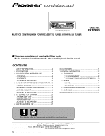
MULTI-CD CONTROL HIGH POWER CASSETTE PLAYER WITH FM/AM TUNER
KEH-P2030
XM/UC
Service
Manual
1
3
6
2
5
4
BASS/TREBLE BOOSTER
BASS/TREBLE BOOSTER
KEH-P2030
KEH-P2030
BAND
BAND
KEH-P2030/XM/UC
KEH-P2035
XM/ES
For details, refer to "Important symbols for good services".
-
This service manual does not describe the CD test mode.
For the operations in the CD test mode, refer to the CD player's Service manual.
CONTENTS
SAFETY INFORMATION
............................................
2
1. SPECIFICATIONS
........................................................
3
2. EXPLODED VIEWS AND PARTS LIST
.......................
6
2.1 PACKING
...............................................................
6
2.2 EXTERIOR
.............................................................
8
2.3 CASSETTE MECHANISM
..................................
10
3. BLOCK DIAGRAM AND SCHEMATIC DIAGRAM ...12
3.1 BLOCK DIAGRAM
..............................................
12
3.2 OVERALL CONNECTION DIAGRAM
.................
14
3.3 KEYBOARD UNIT
...............................................
16
3.4 CASSETTE MECHANISM
..................................
18
4. PCB CONNECTION DIAGRAM
................................
20
4.1 TUNER AMP UNIT
.............................................
20
4.2 KEYBOARD
UNIT
..............................................
24
4.3 CASSETTE MECHANISM
..................................
26
5. ELECTRICAL PARTS LIST
........................................
27
6. ADJUSTMENT
..........................................................
31
7. GENERAL INFORMATION
.......................................
32
7.1 DIAGNOSIS
........................................................
32
7.1.1 DISASSEMBLY
.........................................
32
7.1.2
CONNECTOR FUNCTION DESCRIPTION
...33
7.2 PARTS
.................................................................
34
7.2.1 IC
................................................................
34
7.2.2 DISPLAY
....................................................
38
7.3 OPERATIONAL FLOW CHART
...........................
39
7.4 CLEANING
..........................................................
40
8. OPERATIONS
...........................................................
41