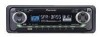
Pioneer KEH-P4020 Other Manual
Pioneer KEH-P4020 - Radio / Cassette Player Manual
 |
UPC - 012562579801
View all Pioneer KEH-P4020 manuals
Add to My Manuals
Save this manual to your list of manuals |
Pioneer KEH-P4020 manual content summary:
- Pioneer KEH-P4020 | Other Manual - Page 1
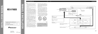
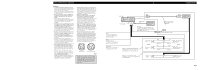
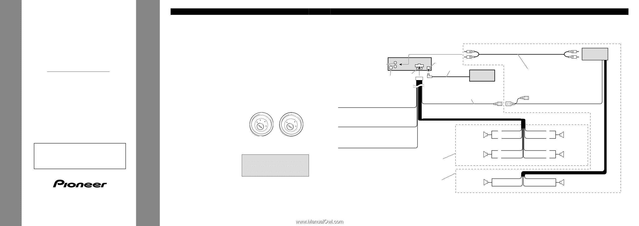
INSTALLATION MANUAL OF OF KEH-P4020 This product conforms to CEMA cord colors. Le code de couleur des câ Installation manuals of both products and connect cords that have the same function. Rear output This Product Fuse Antenna jack IP-BUS input (Blue) IP-BUS cable Multi-CD player - Pioneer KEH-P4020 | Other Manual - Page 2
le manuel d'installation de chacun et effectuez les raccordements en ne tenant compte que de la fonction de chaque câble. Sortie arrière Ce produit Entrée IP-BUS (Bleu) Amplificateur de puissance (vendu séparément) Fusible Jack d'antenne Câble IP-BUS Lecteur de CD à chargeur (vendu - Pioneer KEH-P4020 | Other Manual - Page 3
este producto a otro, refiérase a los manuales de instalación de ambos productos y conecte los cables que tienen la misma función. Salida trasera Este producto Entrada IP-BUS (Azul) Jack para antena Fusible Cable IP-BUS Reproductor de Multi-CD (en venta por separado) Azul/blanco Al - Pioneer KEH-P4020 | Other Manual - Page 4
get in the driver's way and cannot injure the passenger if there is a sudden stop, like an emergency stop. • The semiconductor laser will be damaged if it overheats, so don't install the unit anywhere hot - for instance, near a heater outlet. • If installation angle exceeds 30° from horizontal, the - Pioneer KEH-P4020 | Other Manual - Page 5
de l'installation, ne doit pas dépasser 30° par rapport à l'horizontale, faute de quoi l'unité ne fournira pas ses performances optimales. (Fig. 3) 30˚ Fig. rainure vers le bas.) 2. Fixation de l'appareil au support pour le montage de la radio installée par le constructeur. (Fig. 8) (Fig. 9) Choisir la - Pioneer KEH-P4020 | Other Manual - Page 6
El semiconductor láser se dañará si se sobrecalienta, por eso no instale la unidad en un lugar caliente - por ejemplo, cerca de la salida orificios de tornillo en la ménsula. Fig. 7 10 Ménsula de montaje12de radio existente T11ornillo T13ablero de instrumentos o consola Fig. 8 Fig. 9
-
 1
1 -
 2
2 -
 3
3 -
 4
4 -
 5
5 -
 6
6
 |
 |
Note:
•
This unit is for vehicles with a 12-volt battery and
negative grounding. Before installing it in a recre-
ational vehicle, truck or bus, check the battery
voltage.
•
To avoid shorts in the electrical system, be sure to
disconnect the
≠
battery cable before beginning
installation.
•
Refer to the owner’s manual for details on con-
necting the power amp and other units, then make
connections correctly.
•
Secure the wiring with cable clamps or adhesive
tape. To protect the wiring, wrap adhesive tape
around them where they lie against metal parts.
•
Route and secure all wiring so it cannot touch any
moving parts, such as the gear shift, handbrake and
seat rails. Do not route wiring in places that get
hot, such as near the heater outlet. If the insulation
of the wiring melts or gets torn, there is a danger of
the wiring short-circuiting to the vehicle body.
•
Don’t pass the yellow lead through a hole into the
engine compartment to connect to the battery. This
will damage the lead insulation and cause a very
dangerous short.
•
Do not shorten any leads. If you do, the protection
circuit may fail to work when it should.
•
Never feed power to other equipment by cutting
the insulation of the power supply lead of the unit
and tapping into the lead. The current capacity of
the lead will be exceeded, causing overheating.
•
When replacing fuse, be sure to use only fuse of
the rating prescribed on this unit.
•
Since a unique BPTL circuit is employed, never
wire so the speaker leads are directly grounded or
the left and right
≠
speaker leads are common.
If you ground the products together and the ground
becomes detached, there is a risk of damage to the
products or fire.
•
The black lead is ground. Please ground this lead
separately from the ground of high-current prod-
ucts such as power amps.
•
Speakers connected to this unit must be high-
power types with minimum rating of 45 W and
impedance of 4 to 8 ohms. Connecting speakers
with output and/or impedance values other than
those noted here may result in the speakers catch-
ing fire, emitting smoke, or becoming damaged.
•
When this product’s source is switched ON, a con-
trol signal is output through the blue/white lead.
Connect to an external power amp’s system remote
control or the car’s Auto-antenna relay control ter-
minal (max. 300 mA 12 V DC). If the car features
a glass antenna, connect to the antenna booster
power supply terminal.
•
When an external power amp is being used with
this system, be sure not to connect the blue/white
lead to the amp’s power terminal. Likewise, do not
connect the blue/white lead to the power terminal
of the auto-antenna. Such connection could cause
excessive current drain and malfunction.
•
To avoid short-circuiting, cover the disconnected
lead with insulating tape. Especially, insulate the
unused speaker leads without fail. There is a possi-
bility of short-circuiting if the leads are not insulat-
ed.
•
If this unit is installed in a vehicle that does not
have an ACC (accessory) position on the ignition
switch, the red lead of the unit should be connected
to a terminal coupled with ignition switch ON/OFF
operations. If this is not done, the vehicle battery
may be drained when you are away from the vehi-
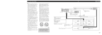
cle for several hours. (Fig. 1)
Fig. 1
•
Cords for this product and those for other prod-
ucts may be different colors even if they have the
same function. When connecting this product to
another product, refer to the supplied Installation
manuals of both products and connect cords that
have the same function.
No ACC position
ACC position
O
N
S
T
A
R
T
O
F
F
A
C
C
O
N
S
T
A
R
T
O
F
F
INSTALLATION MANUAL
MANUEL D’INSTALLATION
<KSNZX/01G00001>
KEH-P4020
Printed in Malaysia
Imprimé en Malaisie
<CZR2945-A/JS> UC
+
≠
+
≠
+
≠
+
≠
+
≠
+
≠
IP-BUS input (Blue)
This Product
Blue/white
To system control terminal of the power amp
or Auto-antenna relay control terminal
(max. 300 mA 12 V DC).
Connecting cords
with RCA pin plugs
(sold separately)
System remote control
Rear speaker
Rear speaker
Right
Front speaker
Rear speaker
White
Gray
White/black
Green
Green/black
Gray/black
Violet
Violet/black
Front speaker
Rear speaker
Left
Perform these connections when using a
different amp (sold separately).
With a 2 speaker system, do not connect
anything to the speaker leads that are not
connected to speakers.
Yellow
To terminal always supplied
with power regardless of
ignition switch position.
Black (ground)
To vehicle (metal) body.
Red
To electric terminal controlled
by ignition switch (12 V DC)
ON/OFF.
Power amp
(sold separately)
Antenna jack
Rear output
Fuse
IP-BUS cable
Multi-CD player
(sold separately)
Fig. 2
<ENGLISH>
Connecting the Units
This product conforms to CEMA cord colors.
Le code de couleur des câbles utilisé pour ce produit est
conforme à CEMA.
Los colores de los cables este producto se conforman
con el código de colores CEMA.