Pioneer P2600 Other Manual
Pioneer P2600 - DEH Radio / CD Player Manual
 |
UPC - 012562667751
View all Pioneer P2600 manuals
Add to My Manuals
Save this manual to your list of manuals |
Pioneer P2600 manual content summary:
- Pioneer P2600 | Other Manual - Page 1
connect cords that have the same function. Multi-CD player (sold separately) IP-BUS cable Rear output This product Fuse Antenna jack IP-BUS input (Blue) Jack for the Wired Remote Control Please see the Instruction Manual for the Wired Remote Control (sold separately). Blue/white To - Pioneer P2600 | Other Manual - Page 2
é aux véhicules avec une bat- terie de 12 V, avec pôle négatif à la masse. Avant de l'installer dans un véhicule de loisir, un camion ou un car, Les haut-parleurs connectés à cet appareil doivent être tels qu'ils puissent supporter une puissance de 50 W, et que leur impédance soit comprise entre 4 - Pioneer P2600 | Other Manual - Page 3
productos pueden ser de colores diferentes aun si tienen la misma función. Cuando se conecta este producto a otro, refiérase a los manuales de ambos productos y conecte los cables que tienen la misma función. Reproductor de Multi-CD (en venta por - Pioneer P2600 | Other Manual - Page 4
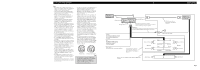
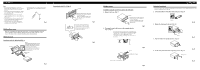
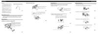
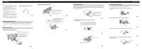
Install as firmly as possible using the top and bottom tabs. To secure, bend the tabs 90 degrees.) 53 Rubber bush Screw Removing the Unit (Fig. 5) (Fig. 6) F5rame I6nsert the release pin If you do not operate the removing and attaching the front panel function, use the supplied fixing screws - Pioneer P2600 | Other Manual - Page 5
aux méthodes de montage illustrées qui suivent. Montage DIN avant Installation avec une bague en caoutchouc (Fig. 4) Tableau de bord 182 53 Support Après avoir introduit le support ves à tête plate (5 × 9 mm), selon le forme des trous de vis sur le support. 10 Fig. 7 Support pour le montage de - Pioneer P2600 | Other Manual - Page 6
ñar a los pasajeros si sucediera un paro repentino, como una detención de emergencia. • El semiconductor láser se dañará si se sobrecalienta, por eso no instale la unidad en un lugar caliente - por ejemplo, cerca de la salida de un calefactor. • Si el ángulo de la instalación excede los 60° del
-
 1
1 -
 2
2 -
 3
3 -
 4
4 -
 5
5 -
 6
6
 |
 |
Note:
•
This unit is for vehicles with a 12-volt battery and
negative grounding. Before installing it in a recre-
ational vehicle, truck or bus, check the battery
voltage.
•
To avoid shorts in the electrical system, be sure to
disconnect the
≠
battery cable before beginning
installation.
•
Refer to the owner’s manual for details on con-
necting the power amp and other units, then make
connections correctly.
•
Secure the wiring with cable clamps or adhesive
tape. To protect the wiring, wrap adhesive tape
around them where they lie against metal parts.
•
Route and secure all wiring so it cannot touch any
moving parts, such as the gear shift, handbrake and
seat rails. Do not route wiring in places that get
hot, such as near the heater outlet. If the insulation
of the wiring melts or gets torn, there is a danger of
the wiring short-circuiting to the vehicle body.
•
Don’t pass the yellow lead through a hole into the
engine compartment to connect to the battery. This
will damage the lead insulation and cause a very
dangerous short.
•
Do not shorten any leads. If you do, the protection
circuit may fail to work when it should.
•
Never feed power to other equipment by cutting
the insulation of the power supply lead of the unit
and tapping into the lead. The current capacity of
the lead will be exceeded, causing overheating.
•
When replacing fuse, be sure to use only fuse of
the rating prescribed on this unit.
•
Since a unique BPTL circuit is employed, never
wire so the speaker leads are directly grounded or
the left and right
≠
speaker leads are common.
If you ground the products together and the ground
becomes detached, there is a risk of damage to the
products or fire.
•
The black lead is ground. Please ground this lead
separately from the ground of high-current prod-
ucts such as power amps.
If you ground the products together and the ground
becomes detached, there is a risk of damage to the
products or fire.
•
Speakers connected to this unit must be high-
power types with minimum rating of 50 W and
impedance of 4 to 8 ohms. Connecting speakers
with output and/or impedance values other than
those noted here may result in the speakers catch-
ing fire, emitting smoke, or becoming damaged.
•
When this product’s source is switched ON, a con-
trol signal is output through the blue/white lead.
Connect to an external power amp’s system remote
control or the car’s Auto-antenna relay control ter-
minal (max. 300 mA 12 V DC). If the car features
a glass antenna, connect to the antenna booster
power supply terminal.
•
When an external power amp is being used with
this system, be sure not to connect the blue/white
lead to the amp’s power terminal. Likewise, do not
connect the blue/white lead to the power terminal
of the auto-antenna. Such connection could cause
excessive current drain and malfunction.
•
To avoid short-circuiting, cover the disconnected
lead with insulating tape. Especially, insulate the
unused speaker leads without fail. There is a possi-
bility of short-circuiting if the leads are not insulat-
ed.
•
If this unit is installed in a vehicle that does not
have an ACC (accessory) position on the ignition
switch, the red lead of the unit should be connected
to a terminal coupled with ignition switch ON/OFF
operations. If this is not done, the vehicle battery
may be drained when you are away from the vehi-
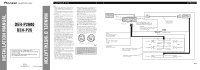
cle for several hours. (Fig. 1)
Fig. 1
•
Cords for this product and those for other prod-
ucts may be different colors even if they have the
same function. When connecting this product to
another product, refer to the supplied manuals of
both products and connect cords that have the
same function.
No ACC position
ACC position
O
N
S
T
A
R
T
O
F
F
A
C
C
O
N
S
T
A
R
T
O
F
F
<KMINX> <03H00001>
DEH-P2600
DEH-P26
Printed in
Imprimé en
<XRD7039-A/JS> UC
+
≠
+
≠
+
≠
+
≠
+
≠
+
≠
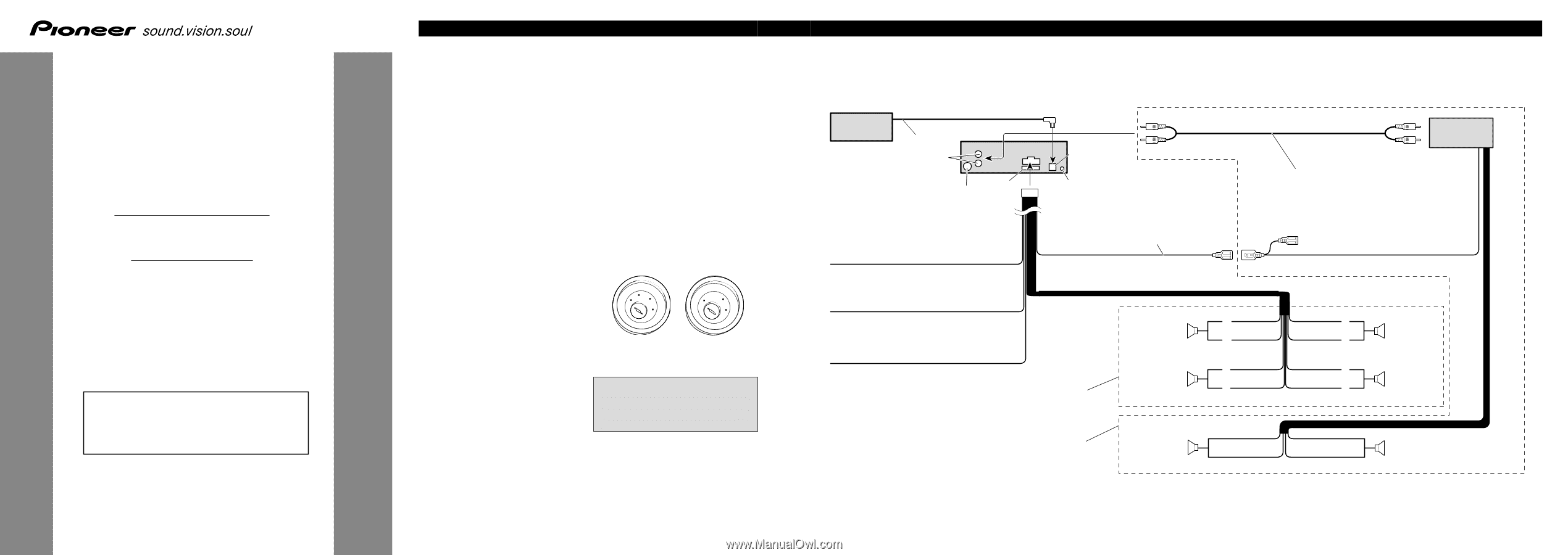
IP-BUS input (Blue)
This product
Blue/white
To system control terminal of the power amp
or Auto-antenna relay control terminal
(max. 300 mA 12 V DC).
Connecting cords
with RCA pin plugs
(sold separately)
System remote control
Rear speaker
Rear speaker
Right
Front speaker
Rear speaker
White
Gray
White/black
Green
Green/black
Gray/black
Violet
Violet/black
Front speaker
Rear speaker
Left
With a 2 speaker system, do not connect
anything to the speaker leads that are not
connected to speakers.
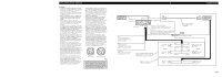
Yellow
To terminal always supplied
with power regardless of
ignition switch position.
Black (ground)
To vehicle (metal) body.
Red
To electric terminal controlled
by ignition switch (12 V DC)
ON/OFF.
Power amp
(sold separately)
Antenna jack
Rear output
Perform these connections when using
the optional amplifier.
Fuse
Jack for the Wired Remote Control
Please see the Instruction Manual for the
Wired Remote Control (sold separately).
IP-BUS cable
Multi-CD player
(sold separately)
Fig. 2
<ENGLISH>
Connecting the Units
This product conforms to CEMA cord colors.
Le code de couleur des câbles utilisé pour ce produit est
conforme à CEMA.
Los colores de los cables este producto se conforman
con el código de colores CEMA.
INSTALLATION MANUAL
MANUEL D’INSTALLATION