Pioneer PD-F607 Service Manual
Pioneer PD-F607 Manual
 |
View all Pioneer PD-F607 manuals
Add to My Manuals
Save this manual to your list of manuals |
Pioneer PD-F607 manual content summary:
- Pioneer PD-F607 | Service Manual - Page 1
FILE-TYPE CD PLAYER PD-F607 PD-F507 ORDER NO. RRV1951 Refer to the service manual RRV1877 for PD-F607/KUXJ and PD-F507/KUXJ. THIS MANUAL IS APPLICABLE TO THE FOLLOWING MODEL(S) AND TYPE(S). Type WYXJ Model PD-F607 PD-F507 O Power Requirement AC220-240V The voltage can be converted by the - Pioneer PD-F607 | Service Manual - Page 2
THIS PIONNER APPARATUS CONTAINS LASER OF CLASS 1. SERVICING OPERATION OF THE APPARATUS SHOULD BE DONE BY A SPECIALLY INSTRUCTED PERSON. LASER DIODE CHARACTERISTICS MAXIMUM OUTPUT POWER : 5 mw WAVELENGTH : 780-785 nm LABEL CHECK (For PD-F607/WYXJ,WVXJ and PD-F507/WPWXJ only) PD-F607/WYXJ only REAR - Pioneer PD-F607 | Service Manual - Page 3
Part No. PD-F607 WYXJ WVXJ Remarks P5-1 P7-16 NSP NSP NSP ASSEMBLES Mother Board Assy Headphone Board Assy Sub Board Assy Power SW Board Assy PWM2199 Not used PWX1540 PWZ3622 PWM2200 PWX1549 PWX1541 PWZ3623 PWM2200 PWX1549 PWX1541 PWZ3623 No.9 P3-1 P3-1 P3-1 PACKING Operating Instructions - Pioneer PD-F607 | Service Manual - Page 4
PD-F607, PD-F507 CONTRAST TABLE (FOR PD-F507) WPWXJ, MAMXJ, RLXJ, RDXJ and KUXJ types are constructed the same except for the following : Part No. Ref. No. Mark Symbol and Description PD-F507 Remarks KUXJ WPWXJ MAMXJ RLXJ RDXJ P5-1 P7-16 NSP NSP ASSEMBLES MOTHER Board Assy SUB Board Assy - Pioneer PD-F607 | Service Manual - Page 5
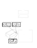
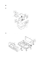
PACKING SECTION No.2 No.1 Remote Control unit Batteery Polyetylene Bag Protecter F Protecter R Warranty Card Operating Instructions Front N0.13 Control Cable No.3 Protecter F Protecter R No.4 PD-F607, PD-F507 Packing Case EXTERIOR and FRONT PANEL SECTION Control Panel No.12 Rear - Pioneer PD-F607 | Service Manual - Page 6
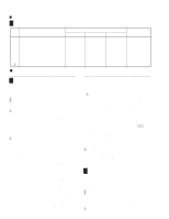
PD-F607, PD-F507 CONTRAST OF PCB ASSEMBLIES J F MOTHER BOARD ASSY ASSY (For PD-F507) PWM2197, PWM2195 and PWM2196 are constructed the same except for the following : Mark Symbol and Description PWM2196 Part F MOTHER BOARD ASSY (PWM2200: For PDF-607/WYXJ) SEMICONDUCTORS IC406 IC151 IC301 IC31, - Pioneer PD-F607 | Service Manual - Page 7
HLEM38S-1 RKP-533 VKN1201 PKB1023 Mark No. Description Part No. JA321 X401 X351 OPTICAL OUTPUT JACK TERMINAL 2P CRYSTAL RESONATOR (16.9344MHz) CRYSTAL RESONATOR (4.194MHz) TOTX178 RKC-061 PSS1008 VSS1014 K HEADPHONE BOARD ASSY (PD-F607 only) COILS L501,L506,L507 CAPACITORS C501,C502 C507 - Pioneer PD-F607 | Service Manual - Page 8
STBL CN351 PD-F607:HLEM38S-1 PD-F507:HLEM34S-1 J801 D20PWW0545E D CF RSG1030 D751 SLR-342VCT31 B 5 J801 B CN701 POWER SW ASSY PWZ3623 NOTE: The numbers marked with a circle show the number of each 8 CF JF measuring point,which correspond to the number in the service manual PD-F607(ORDER - Pioneer PD-F607 | Service Manual - Page 9
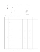
5 6 7 8 NOTE: When ordering service parts, be sure to refer to "PARTS LIST of EXPLODED VIEWS" or "PCBPARTS LIST". PD-F607, PD-F507 IC301 (CXD2529Q) PIN No. 1 2to4 7 8 9 10 11 12 13 14 16 17 23 24 25 26 27 38 39 40 41 42 43 Voltage(V) 5 0 4.7 1.2-1. - Pioneer PD-F607 | Service Manual - Page 10
1 2 3 4 PD-F607, PD-F507 PCB DIAGRAMS A NOTE FOR PCB DIAGRAMS: 1. Part numbers in PCB diagrams match those in the schematic diagrams. 2. A comparison between the main parts of PCB and schematic diagrams is shown below. Symbol in PCB Symbol in Schematic Diagrams Diagrams Part Name B C EB
-
 1
1 -
 2
2 -
 3
3 -
 4
4 -
 5
5 -
 6
6 -
 7
7 -
8
-
9
-
10
 |
 |
ORDER NO.
PIONEER ELECTRONIC CORPORATION
4-1, Meguro 1-Chome, Meguro-ku, Tokyo 153-8654, Japan
PIONEER ELECTRONICS SERVICE, INC.
P.O. Box 1760, Long Beach, CA 90801-1760, U.S.A.
PIONEER ELECTRONIC (EUROPE) N.V .
Haven 1087, Keetberglaan 1, 9120 Melsele, Belgium
PIONEER ELECTRONICS ASIACENTRE
PTE. LTD.
501 Orchard Road, #10-00 Lane Crawford Place, Singapore 0923
C
PIONEER ELECTRONIC CORPORATION
1998
FILE-TYPE CD PLAYER
RRV1951
PD-F607
T–ZZY
APR. 1998
Printed in Japan
Refer to the service manual RRV1877 for PD-F607/KUXJ and
PD-F507/KUXJ.
CONTENTS
1. SAFETY INFORMATION
....................................
2
2. CONTRAST OF MISCELLANEOUS PARTS
.....
3
3. SCHEMATIC AND PCB DIAGRAMS
.................
8
THIS MANUAL IS APPLICABLE TO THE FOLLOWING MODEL(S) AND TYPE(S).
Model
PD-F607
PD-F507
Type
The voltage can be converted by
the following method.
Power Requirement
WYXJ
O
AC220-240V
WVXJ
O
AC220-240V
WPWXJ
O
AC220-240V
MAMXJ
O
AC220-230V
RLXJ
O
AC110-120V/220-240V
With the voltage selector
RDXJ
O
AC110-127V/220-240V
With the voltage selector
PD-F507