Pioneer PWM-F110 Owner's Manual
Pioneer PWM-F110 - Bracket For Plasma Panel Manual
 |
UPC - 012563011829
View all Pioneer PWM-F110 manuals
Add to My Manuals
Save this manual to your list of manuals |
Pioneer PWM-F110 manual content summary:
- Pioneer PWM-F110 | Owner's Manual - Page 1
INSTALLATION MANUAL IN-PWMF110.R1 PWM-F110 Premier Mounts 3130 E. Miraloma Avenue Anaheim, CA 92806 Phone: (800) 368-9700 Fax: (800) 832-4888 [email protected] www.mounts.com - Pioneer PWM-F110 | Owner's Manual - Page 2
PBL-110 Projector Mount Page - 2 - Installation Manual - Pioneer PWM-F110 | Owner's Manual - Page 3
PWM-F110 Table of Contents Warning Statements ...- 4 Parts List ...- 6 Installation Tools ...- 6 Mounting Bracket Installation ...- 7 Wall Stud Location ...- 10 Installing the Flat Panel Display ...- 14 Technical Specifications ...- 16 Warranty ...- 17 Contact Premier Mounts ...- 17 Notes ...- 18 - - Pioneer PWM-F110 | Owner's Manual - Page 4
read, understood and followed to prevent personal injury or property damage. Keep these installation instructions in an easily accessible location for future reference. The wall being considered for mounting must be capable of supporting at least five (5) times the weight of 40Kg. If it is not, the - Pioneer PWM-F110 | Owner's Manual - Page 5
come included in this package and that it only be used in conjunction with the appropriate plasma television. The PWM-F110 plasma wall mount is to be used to attach a plasma television vertically to an appropriate wall. In order to mount the plasma television, it is necessary to attach the enclosed - Pioneer PWM-F110 | Owner's Manual - Page 6
PWM-F110 Parts List NOTE: This wall mount is shipped with all proper installation hardware and components. Make sure that none of these parts are missing and/or damaged before beginning installation. If there are parts missing and/or damaged, please stop the installation and contact Premier Mounts ( - Pioneer PWM-F110 | Owner's Manual - Page 7
PWM-F110 Mounting Bracket Installation NOTE: Proper installation procedure by qualified personnel as outlined in the installation instructions must be adhered to. Failure to do so could result in serious personal injury and possible damage to the flat panel. WARNING: INVERT THE FLAT PANEL AND PLACE - Pioneer PWM-F110 | Owner's Manual - Page 8
PWM-F110 3. Lay the mounting brackets on the back of the display (stamped arrows facing out) - (Figure 3). Mounting Brackets Figure 3 Bottom of Flat Panel 4. Match the center of viewing guide with the centerline you marked in step 1 (Figure 4). 5 The mounting brackets are designed with a center - Pioneer PWM-F110 | Owner's Manual - Page 9
PWM-F110 Mounting Bracket CL Bottom of Flat Panel Center of Viewing Guide Align the Mounting Brackets Figure 4 Bottom of the Flat Panel Figure 5 Center of Flat Panel 6. The Griplates™ have M4, M5, M6 and M8 hole patterns to fit the hardware that your flat panel requires. EXAMPLE: If your - Pioneer PWM-F110 | Owner's Manual - Page 10
PWM-F110 Wall Stud Location 1. Using a (commercially available) wood stud finder, locate two 16" or 24" stud centers behind the wall. Once found, make a pencil marking on the center of the wood studs (Figure 8). NOTE: The wall plates have (3) 16" and (1) 24" mounting slot positions (see - Pioneer PWM-F110 | Owner's Manual - Page 11
PWM-F110 3. Place the bottom portion of the wall plate to the reference line and mark the four (4) lag bolt mounting points through the wall plate slots on the wall. 4. Level the wall plate with the reference arrow pointing up to the ceiling (Figure 10). Mounting Surfaces Wood studs: Drill four - Pioneer PWM-F110 | Owner's Manual - Page 12
PWM-F110 5. Level and secure the plate to the wall with the reference arrow facing up to the ceiling. 6. Secure the plate using the four (4) 5/16" lag bolts and flat washers (supplied) -Figure 12. CAUTION: Do not over tighten the lag bolts. NOTE: Use a minimum diameter of 5/16" x 3" long wood screws - Pioneer PWM-F110 | Owner's Manual - Page 13
PWM-F110 7. Level and secure the plate to the wall with the reference arrow facing up to the ceiling. 8. Use a (commercially available). 5/16" x 2 ¼" wedge anchors (commercially available) Wall Plate Figure 13 5/16" x 2 ¼" wedge anchors (commercially available) Installation Manual Page - 13 - - Pioneer PWM-F110 | Owner's Manual - Page 14
PWM-F110 Installing the Flat Panel Display WARNING: AT LEAST (2) QUALIFIED PERSONNEL ARE STRONGLY RECOMMENDED FOR INSTALLATION OF THIS PRODUCT. FAILURE TO DO SO COULD RESULT IN SERIOUS INJURY AND POSSIBLE DAMAGE TO THE FLAT PANEL. 1. Raise the flat panel with the mounting brackets secured to the - Pioneer PWM-F110 | Owner's Manual - Page 15
PWM-F110 2. Make any lateral shift adjustments and lock it by tightening the two (2) ¼"-20 Phillips screws found on the bottom of the mounting brackets. Use the wall bumper to adjust your flat panel. CAUTION: Do not over tighten the ¼"-20 screws to the rods (Figure 15). NOTE: To remove the flat - Pioneer PWM-F110 | Owner's Manual - Page 16
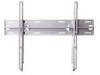
PWM-F110 Technical Specifications (406.4) (406.4) (711.2) (406.4) A. Wall plate B. Mounting brackets C. ¼" x 20 Safety screws D. Leveling feet (88.9) (31.75) (606.92) (49.53) (127) Page 16 (36.91) Figure 16 Installation Manual - Pioneer PWM-F110 | Owner's Manual - Page 17
injury. Contact Premier Mounts In the event of missing and/or damaged equipment, or technical questions, the following information can help in the completion of the installation. Customer Service - (800) 368-9700 Ext. 224 Technical Support - [email protected] Installation Manual Page 17 - Pioneer PWM-F110 | Owner's Manual - Page 18
PWM-F110 Notes IN-PWMF110.R1 Page - 18 - Premier Mounts 3130 E. Miraloma Avenue Anaheim, CA 92806 Phone: (800) 368-9700 Fax: (800) 832-4888 [email protected] www.mounts.com Installation Manual
-
 1
1 -
 2
2 -
 3
3 -
 4
4 -
 5
5 -
 6
6 -
 7
7 -
8
-
9
-
10
-
11
-
12
-
13
-
14
-
15
-
16
-
17
-
18
 |
 |

INSTALLATION MANUAL
PWM-F110
Premier Mounts
3130 E. Miraloma Avenue
Anaheim, CA 92806
Phone: (800) 368-9700
Fax: (800) 832-4888
www.mounts.com
IN-PWMF110.R1