Pioneer SC-27 Owner's Manual - Page 30
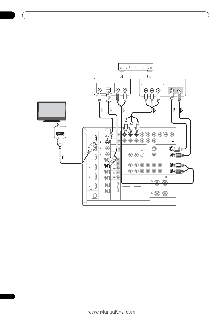
Connecting your DVD player with no HDMI output
 |
UPC - 012562957487
View all Pioneer SC-27 manuals
Add to My Manuals
Save this manual to your list of manuals |
Page 30 highlights
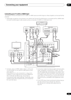
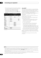
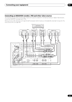
03 Connecting your equipment Connecting your DVD player with no HDMI output This diagram shows connections of a TV (with HDMI input) and DVD player (or other playback component with no HDMI output) to the receiver. DVD player, etc. HDMI/DVI-compatible monitor or flat panel TV Select one DIGITAL OUT AUDIO OUT COAXIAL OPTICAL R ANALOG L Select one COMPONENT VIDEO OUT PR PB Y VIDEO OUT S-VIDEO VIDEO HDMI IN HDMI OUT 1 (KURO LINK ) OUT 2 XM IN COAXIAL ASSIGNABLE IN 1 (DVD) IN 2 (CD) BD IN IN 1 IN 2 IN 3 ASSIGNABLE 1-3 LAN (10/100) IN 3 (VIDEO 2) IN 1 (TV/SAT) IN 2 (DVR) IN 3 (VIDEO1) IN 4 (CD-R) ASSIGNABLE OUT 1 OUT 2 OPTICAL 12 V TRIGGER (OUTPUT 12V TOTAL 50 mA MAX) SIRIUS IN 1 IN 1 (DVD) 2 PR PB Y ZONE 2 OUT IN 2 IN 3 (DVR) PR PB Y MONITOR OUT SIGNAL GND PR PB Y (VIDEO 1) ASSIGNABLE 1 - 3 COMPONENT VIDEO S-VIDEO IR IN 1 IN 2 OUT IN CONTROL OUT VIDEO ZONE 2 ZONE 3 PHONO CD OUT OUT IN IN L VIDEO CD-R/TAPE OUT IN DVD T IN R SPEAKERS Class 2 Wiring R SURROUND BACK/ B L (Single) SELECTABLE SEE INSTRUCTION MANUAL CAUTION: SPEAKER IMPEDANCE 6 Ω - 16 Ω . ATTENTION: ENCEINTE D'IMPEDANCE DE 6 Ω - 16 Ω . SELECTABLE VOIR LE MODE D'EMPLOI RS-232C • If you want to listen to the sound of the TV over the receiver, connect the receiver and TV with audio cables. • Component video should give superior picture quality when compared to composite or S-Video. You can also take advantage of progressive scan video (if your source and TV are both compatible), which delivers a very stable, flicker-free picture. See the manuals that came with your TV and source component to check whether they are compatible with progressive-scan video. • If your DVD player offers multi-channel analog audio outputs, see Connecting the multichannel analog inputs on page 34. 30 en
-
 1
1 -
2
-
3
-
4
-
5
-
6
-
7
-
8
-
9
-
10
-
11
-
12
-
13
-
14
-
15
-
16
-
17
-
18
-
19
-
20
-
21
-
22
-
23
-
24
-
 25
25 -
 26
26 -
 27
27 -
 28
28 -
 29
29 -
 30
30 -
 31
31 -
 32
32 -
 33
33 -
 34
34 -
 35
35 -
36
-
37
-
38
-
39
-
40
-
41
-
42
-
43
-
44
-
45
-
46
-
47
-
48
-
49
-
50
-
51
-
52
-
53
-
54
-
55
-
56
-
57
-
58
-
59
-
60
-
61
-
62
-
63
-
64
-
65
-
66
-
67
-
68
-
69
-
70
-
71
-
72
-
73
-
74
-
75
-
76
-
77
-
78
-
79
-
80
-
81
-
82
-
83
-
84
-
85
-
86
-
87
-
88
-
89
-
90
-
91
-
92
-
93
-
94
-
95
-
96
-
97
-
98
-
99
-
100
-
101
-
102
-
103
-
104
-
105
-
106
-
107
-
108
-
109
-
110
-
111
-
112
-
113
-
114
-
115
-
116
-
117
-
118
-
119
-
120
-
121
-
122
-
123
-
124
-
125
-
126
-
127
-
128
-
129
-
130
-
131
-
132
-
133
-
134
-
135
-
136
-
137
-
138
-
139
-
140
-
141
-
142
-
143
-
144
-
145
-
146
-
147
-
148
-
149
-
150
-
151
-
152
-
153
-
154
 |
 |