Pioneer SC-27 Owner's Manual - Page 48
Problems when using the Auto MCACC Setup, The Input Setup menu, Input Setup
 |
UPC - 012562957487
View all Pioneer SC-27 manuals
Add to My Manuals
Save this manual to your list of manuals |
Page 48 highlights
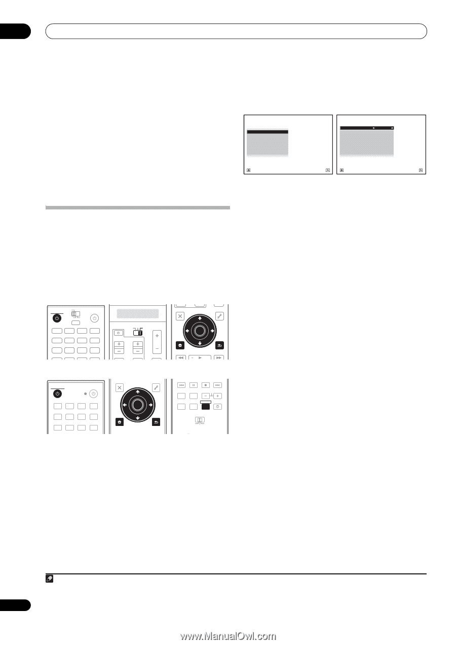
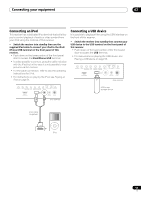
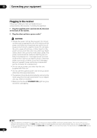
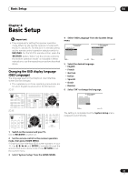
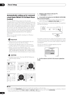
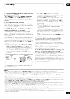
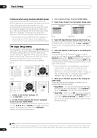
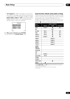
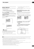
04 Basic Setup Problems when using the Auto MCACC Setup If the room environment is not optimal for the Auto MCACC Setup (too much background noise, echo off the walls, obstacles blocking the speakers from the microphone) the final settings may be incorrect. Check for household appliances (air conditioner, fridge, fan, etc.), that may be affecting the environment and switch them off if necessary. If there are any instructions showing in the front panel display, please follow them. • Some older TVs may interfere with the operation of the microphone. If this seems to be happening, switch off the TV when doing the Auto MCACC Setup. The Input Setup menu You only need to make settings in the Input Setup menu if you didn't hook up your digital equipment according to the default settings (see Input function default and possible settings on page 49). In this case, you need to tell the receiver what equipment is hooked up to which terminal so the buttons on the remote control correspond to the components you've connected. SC-27: RECEIVER MAIN ZONE2 SOURCE 3 MULTI OPERATION DVD BD TV DVR HOME MEDIA VIDEO1 VIDEO2 HDMI GALLERY USB iPod CD CD-R TUNER MULTI CH PHONO IN XM SIRIUS SC-25: TV SOURCE RECEIVER CH VOL VOL TV CONTROL INPUT AUDIO PARAMETER LIST TOP MENU BAND PRESET MUTE TUNE MUTE VIDEO PARAMETER TOOLS ENTER T.EDIT GUIDE PRESET CATEGORY HOME MENU iPod CTRL TUNE STATUS PHASE CTRL RETURN CH LEVEL RECEIVER SOURCE DVD BD DVR HDMI HOME MEDIA TV CD CD-R GALLERY iPod USB TUNER XM SIRIUS INPUT AUDIO PARAMETER LIST VIDEO PARAMETER TUNE TOOLS TOP MENU BAND T.EDIT GUIDE PRESET ENTER PRESET CATEGORY HOME MENU TUNE iPod CTRL RETURN ANT MPX PQLS MEMORY AUDIO INFO CH DISP MULTI OPE TV CTRL RECEIVER REMOTE SETUP ZONE 2 ZONE 3 MAIN 1 Switch on the receiver and your TV. Use RECEIVER to switch on. 2 Set the remote control to the receiver operation mode, then press HOME MENU. A Graphical User Interface (GUI) screen appears on your TV. Use and ENTER to navigate through the screens and select menu items. Press RETURN to confirm and exit the current menu. 3 Select 'System Setup' from the HOME MENU. 4 Select 'Input Setup' from the System Setup menu. 4.SystemSetup A/V RECEIVER a.Manual SP Setup b. Input Setup c. OSD Language d. Other Setup 4b.Input Setup A/V RECEIVER Input Input Name Input Skip : DVD : Rename : OFF Digital In : HDMI Input : Component In : 12V Trigger1 : 12V Trigger2 : COAX-1 --- Comp-1 OFF OFF Exit Return Exit Finish 5 Select the input function that you want to set up. The default names correspond with the names next to the terminals on the rear panel (such as DVD or VIDEO1) which, in turn, correspond with the names on the remote control. 6 Select the input(s) to which you've connected your component. For example, if your DVD player only has an optical output, you will need to change the DVD input function's Digital In setting from COAX-1 (default) to the optical input you've connected it to. The numbering (OPT-1 to 4) corresponds with the numbers beside the inputs on the back of the receiver. • If your component is connected via a component video cable to an input terminal other than the default, you must tell the receiver which input terminal your component is connected to, or else you may see the S-Video or composite video signals instead of the component video signals.1 7 When you're finished, proceed to the settings for other inputs. There are three optional settings in addition to the assignment of the input jacks: • Input Name - You can choose to rename the input function for easier identification. Select Rename to do so, or Default to return to the system default. • Input Skip - When set to ON, that input is skipped when selecting the input using INPUT SELECT or the front panel INPUT SELECTOR dial. (DVD and other inputs can be still be selected directly with the input function buttons.) Note 1 For high-definition video (using component video connections), or when digital video conversion is switched off (in Setting the Video options on page 90), you must connect your TV to this receiver using the same type of video cable as you used to connect your video component. 48 en
-
 1
1 -
2
-
3
-
4
-
5
-
6
-
7
-
8
-
9
-
10
-
11
-
12
-
13
-
14
-
15
-
16
-
17
-
18
-
19
-
20
-
21
-
22
-
23
-
24
-
25
-
26
-
27
-
28
-
29
-
30
-
31
-
32
-
33
-
34
-
35
-
36
-
37
-
38
-
39
-
40
-
41
-
42
-
 43
43 -
 44
44 -
 45
45 -
 46
46 -
 47
47 -
 48
48 -
 49
49 -
 50
50 -
 51
51 -
 52
52 -
 53
53 -
54
-
55
-
56
-
57
-
58
-
59
-
60
-
61
-
62
-
63
-
64
-
65
-
66
-
67
-
68
-
69
-
70
-
71
-
72
-
73
-
74
-
75
-
76
-
77
-
78
-
79
-
80
-
81
-
82
-
83
-
84
-
85
-
86
-
87
-
88
-
89
-
90
-
91
-
92
-
93
-
94
-
95
-
96
-
97
-
98
-
99
-
100
-
101
-
102
-
103
-
104
-
105
-
106
-
107
-
108
-
109
-
110
-
111
-
112
-
113
-
114
-
115
-
116
-
117
-
118
-
119
-
120
-
121
-
122
-
123
-
124
-
125
-
126
-
127
-
128
-
129
-
130
-
131
-
132
-
133
-
134
-
135
-
136
-
137
-
138
-
139
-
140
-
141
-
142
-
143
-
144
-
145
-
146
-
147
-
148
-
149
-
150
-
151
-
152
-
153
-
154
 |
 |