Pioneer SC-55 Owner's Manual - Page 24
Select one
 |
View all Pioneer SC-55 manuals
Add to My Manuals
Save this manual to your list of manuals |
Page 24 highlights
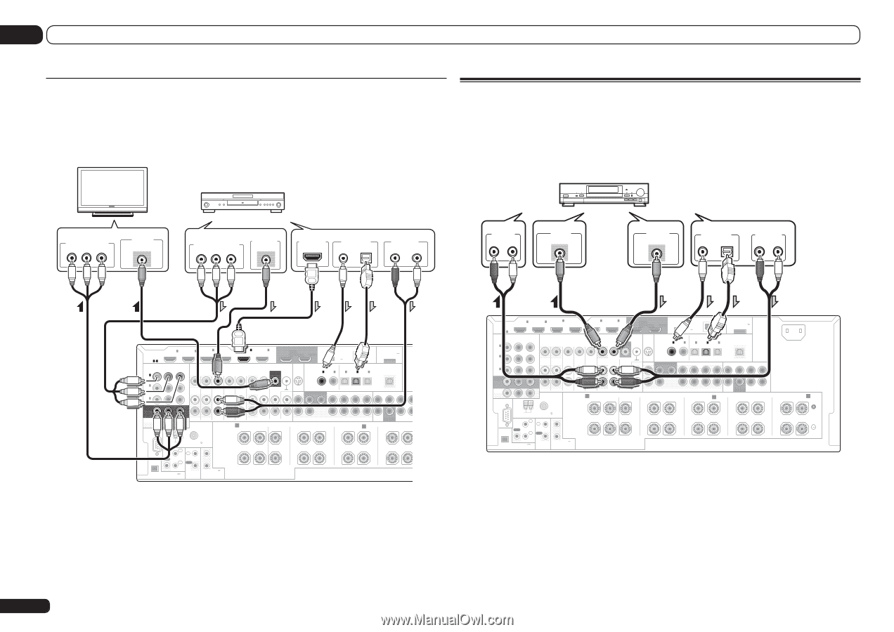
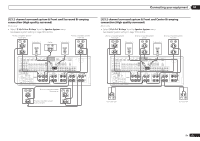
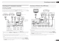
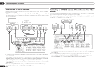
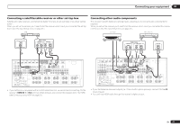
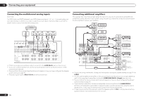
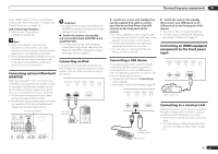
03 Connecting your equipment Connecting your TV with no HDMI input This diagram shows connections of a TV (with no HDMI input) and DVD player (or other playback component) to the receiver. ! With these connections, the picture is not output to the TV even if the DVD player is connected with an HDMI cable. Connect the receiver and TV using the same type of video cable as used to connect the receiver and player. DVD player, etc. Connecting an HDD/DVD recorder, BD recorder and other video sources This receiver has two sets of audio/video inputs and outputs suitable for connecting analog or digital video devices, including HDD/DVD recorders and BD recorders. When you set up the receiver you'll need to tell the receiver which input you connected the recorder to (see also The Input Setup menu on page 34 ). HDD/DVD recorder, BD recorder, etc. TV Select one COMPONENT VIDEO IN VIDEO IN Y PB PR VIDEO Select one COMPONENT VIDEO OUT Y PB PR VIDEO OUT VIDEO HDMI OUT Select one DIGITAL OUT COAXIAL OPTICAL AUDIO OUT R ANALOG L AUDIO IN R ANALOG L VIDEO IN VIDEO VIDEO OUT VIDEO Select one DIGITAL OUT AUDIO OUT COAXIAL OPTICAL R ANALOG L IN 1 IN 2 HDMI ASSIGNABLE 16 ASSIGNABLE Y COMPONENT VIDEO PB PR IN 1 (DVD) IN 4 (VIDEO) BD IN IN 5 (DVD) IN 6 (DVR/BDR) OUT 1 (CONTROL) OUT 2 DC OUTPUT for WIRELESS LAN (OUTPUT 5 V 0.6 A MAX) LAN (10/100) VIDEO SIRIUS COAXIAL ASSIGNABLE OPTICAL ASSIGNABLE MONITOR SIGNAL IN OUT GND IN 1 IN 2 IN 1 IN 2 IN 3 (DVD) (CD) (TV/SAT) (DVR/BDR) (VIDEO) ADAPTER PORT (OUTPUT 5 V 0.1 A MAX) OUT IN 2 (DVR/ BDR) IN 3 (VIDEO) MONITOR OUT ZONE 2 ZONE 3 DVD TV/SAT VIDEO DVR/BDR PHONO OUT OUT IN IN IN OUT IN IN CD IN FRONT 1 SUBWOOFER 2 SURROUND SURR BACK F HEIGHT (Single) F WIDE FRONT CENTER SURROUND SURR B ZONE2 OUT RS-232C A FRONT R AUDIO CENTER CENTER L FRONT HEIGHT R L PRE OUT FRONTWIDE / B R L SUBWOOFER MULTI C SURROUND R AM LOOP ANTENNA FM UNBAL 75 IR IN 1 IN 1 SPEAKERS OUT IN 2 OUT 2 (OUTPUT 12 V (OUTPUT 5 V TOTAL 150 mA MAX) EXTENSION 150 mA MAX) CONTROL 12VTRIGGER ! Connect using an HDMI cable to listen to HD audio on the receiver. Do not use an HDMI cable to input video signals. Depending on the video component, it may not be possible to output signals connected by HDMI and other methods simultaneously, and it may be necessary to make output settings. Please refer to the operating instructions supplied with your component for more information. ! If you want to listen to the sound of the TV over the receiver, connect the receiver and TV with audio cables (page 23). ! If you use an optical digital audio cable, you'll need to tell the receiver which digital input you connected the player to (see The Input Setup menu on page 34 ). 24 En IN 1 IN 2 HDMI ASSIGNABLE 16 ASSIGNABLE Y COMPONENT VIDEO PB PR IN 1 (DVD) IN 4 (VIDEO) BD IN IN 5 (DVD) IN 6 (DVR/BDR) OUT 1 (CONTROL) OUT 2 DC OUTPUT for WIRELESS LAN (OUTPUT 5 V 0.6 A MAX) LAN (10/100) VIDEO SIRIUS COAXIAL ASSIGNABLE OPTICAL ASSIGNABLE MONITOR SIGNAL IN OUT GND IN 1 IN 2 IN 1 IN 2 IN 3 (DVD) (CD) (TV/SAT) (DVR/BDR) (VIDEO) ADAPTER PORT (OUTPUT 5 V 0.1 A MAX) OUT AC IN IN 2 (DVR/ BDR) IN 3 (VIDEO) MONITOR OUT ZONE 2 ZONE 3 DVD TV/SAT VIDEO OUT OUT IN IN IN DVR/BDR OUT IN PHONO IN CD IN FRONT 1 SUBWOOFER 2 SURROUND SURR BACK F HEIGHT (Single) F WIDE FRONT CENTER SURROUND SURR BACK L R ZONE2 OUT RS-232C A FRONT R AUDIO CENTER CENTER L FRONT HEIGHT R L PRE OUT FRONTWIDE / B R L SUBWOOFER MULTI CH IN SURROUND R L SURROUND BACK A R L (Single) AM LOOP ANTENNA FM UNBAL 75 IR IN 1 IN 1 SPEAKERS OUT IN 2 OUT 2 (OUTPUT 12 V (OUTPUT 5 V TOTAL 150 mA MAX) EXTENSION 150 mA MAX) CONTROL 12VTRIGGER ! In order to record, you must connect the analog audio cables (the digital connection is for playback only) (page 60). ! If your HDD/DVD recorder, BD recorder, etc., is equipped with an HDMI output terminal, we recommend connecting it to the receiver's HDMI DVR/BDR IN terminal. When doing so, also connect the receiver and TV by HDMI (see Connecting using HDMI on page 23 ).
-
 1
1 -
2
-
3
-
4
-
5
-
6
-
7
-
8
-
9
-
10
-
11
-
12
-
13
-
14
-
15
-
16
-
17
-
18
-
 19
19 -
 20
20 -
 21
21 -
 22
22 -
 23
23 -
 24
24 -
 25
25 -
 26
26 -
 27
27 -
 28
28 -
 29
29 -
30
-
31
-
32
-
33
-
34
-
35
-
36
-
37
-
38
-
39
-
40
-
41
-
42
-
43
-
44
-
45
-
46
-
47
-
48
-
49
-
50
-
51
-
52
-
53
-
54
-
55
-
56
-
57
-
58
-
59
-
60
-
61
-
62
-
63
-
64
-
65
-
66
-
67
-
68
-
69
-
70
-
71
-
72
-
73
-
74
-
75
-
76
-
77
-
78
-
79
-
80
-
81
-
82
-
83
-
84
-
85
-
86
-
87
-
88
-
89
-
90
-
91
-
92
-
93
-
94
-
95
-
96
-
97
-
98
-
99
-
100
-
101
-
102
-
103
-
104
-
105
-
106
-
107
-
108
 |
 |