Pioneer SC-55 Owner's Manual - Page 28
Connect a separate amplifier to
 |
View all Pioneer SC-55 manuals
Add to My Manuals
Save this manual to your list of manuals |
Page 28 highlights
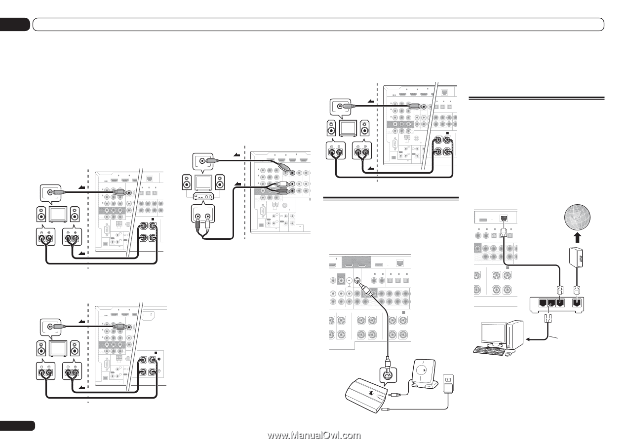
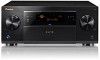
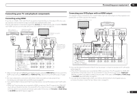
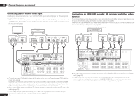
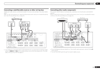
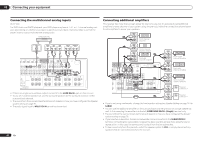
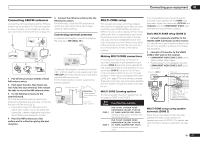
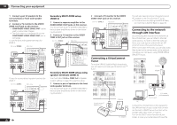
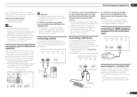
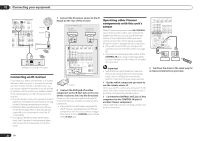
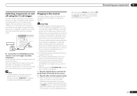
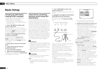
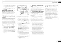
03 Connecting your equipment 1 Connect a pair of speakers to the surround back or front wide speaker terminals. 2 Connect a TV monitor to the VIDEO ZONE 2 OUT jack on this receiver. ! COMPONENT VIDEO ZONE 2 OUT can be used to output clear images. ! The GUI screen is not displayed if only the COMPONENT VIDEO ZONE 2 OUT jack is connected. To use the front wide speaker terminals for ZONE 2: Sub zone (ZONE 2) Main zone VIDEO IN L R IN 1 HDMI ASSIGNABLE 16 IN D2C OUTPUT(INVID r WIRELESS LAN (OUTPUT 5 V 0.6 A MAX) LAN (10/100) ASSIGNABLE COMPONENT VIDEO SIGNABLE OPTICAL ASSIGNABLE Y IN 1 (DVD) PB PR 1 IN 2 IN 1 IN 2 IN 3 D) (CD) (TV/SAT) (DVR/BDR) (VIDEO) ADA (O IN 2 (DVR/ BDR) IN 3 (VIDEO) MONITOR OUT ZONE 2 ZONE 3 OUT2 SURROOUUTND SURR BACK F HEIGHT (Single) F WIDE FRONT ZONE2 OUT RS-232C PRE OUT FRONTWIDE / B L R L AM LOOP ANTENNA FM UNBAL 75 IR IN 1 IN 1 OUT IN 2 OUT 2 (OUTPUT (OUTPUT 5 V TOTAL 15 EXTENSION 150 mA MAX) CONTROL 12VTR To use the surround back speaker terminals for ZONE 2: Sub zone (ZONE 2) Main zone VIDEO IN L R IN 1 IN 2 HDMI ASSIGNABLE 16 ASSIGNABLE Y COMPONENT VIDEO PB PR IN 1 (DVD) IN (VID AC IN IN 2 (DVR/ BDR) IN 3 (VIDEO) MONITOR OUT ZONE 2 ZONE 3 OUTACK OUT L R ZONE2 OUT RS-232C H IN L SURROUND BACK A R L (Single) AM LOOP ANTENNA FM UNBAL 75 IR IN 1 IN 1 OUT IN 2 OUT 2 (OUTPUT (OUTPUT 5 V TOTAL 15 EXTENSION 150 mA MAX) CONTROL 12VTR 28 En Secondary MULTI-ZONE setup (ZONE 3) 1 Connect a separate amplifier to the AUDIO ZONE 3 OUT jacks on this receiver. You should have a pair of speakers attached to the sub zone amplifier as shown in the following illustration. 2 Connect a TV monitor to the VIDEO ZONE 3 OUT jack on this receiver. Sub zone (ZONE 3) VIDEO IN AUDIO IN R L Main zone IN 1 IN 2 HDMI ASSIGNABLE 16 ASSIGNABLE Y COMPONENT VIDEO PB PR IN 1 (DVD) IN 4 (VIDEO) BD IN IN 2 (DVR/ BDR) IN 3 (VIDEO) MONITOR OUT ZONE 2 ZONE 3 DVD TV/SAT V OUT OUT IN IN ZONE2 OUT A RS-232C R AM LOOP ANTENNA FM UNBAL 75 IR IN 1 IN 1 SPEAKERS OUT IN 2 OUT 2 (OUTPUT 12 V (OUTPUT 5 V TOTAL 150 mA MAX) EXTENSION 150 mA MAX) CONTROL 12VTRIGGER Secondary MULTI-ZONE setup using speaker terminals (ZONE 3) You must select 5.1ch + ZONE 2+3 in Speaker system setting on page 76 to use this setup. 1 Connect a pair of speakers to the front wide speaker terminals. You should have a pair of speakers attached to the sub zone amplifier as shown in the following illustration. 2 Connect a TV monitor to the VIDEO ZONE 3 OUT jack on this receiver. Sub zone (ZONE 3) Main zone VIDEO IN L R IN 1 IN 2 HDMI ASSIGNABLE 16 ASSIGNABLE Y COMPONENT VIDEO PB PR IN 1 (DVD) DC(INVOIDU4TEPOU)T WIRELESS LAN (OUTPUT 5 V 0.6 A MAX) AD LAN (10/100) GNABLE OPTICAL ASSIGNABLE IN 2 IN 1 IN 2 IN 3 ) (CD) (TV/SAT) (DVR/BDR) (VIDEO) IN 2 (DVR/ BDR) IN 3 (VIDEO) MONITOR OUT ZONE 2 ZONE 3 DVD T OUT OUT2 SURROIUNND SURR BACK F HEIGHT (Single) F WIDE FRONT ZONE2 OUT RS-232C PRE OUT FRONTWIDE / B L R L AM LOOP ANTENNA FM UNBAL 75 IR IN 1 IN 1 SPEAKER OUT IN 2 OUT 2 (OUTPUT 12 V (OUTPUT 5 V TOTAL 150 mA MAX) EXTENSION 150 mA MAX) CONTROL 12VTRIGGER Connecting a SiriusConnect Tuner To receive SIRIUS Satellite Radio broadcasts, you will need to activate your SiriusConnectTM tuner. IN 6 (DVR/BDR) OUT 1 (CONTROL) OUT 2 DC OUTPUT for WIRELESS LAN (OUTPUT 5 V 0.6 A MAX) LAN (10/100) VIDEO SIRIUS COAXIAL ASSIGNABLE OPTICAL ASSIGNABLE MONITOR SIGNAL IN OUT GND IN 1 IN 2 IN 1 IN 2 IN 3 (DVD) (CD) (TV/SAT) (DVR/BDR) (VIDEO) /BDR IN PHONO IN CD IN FRONT 1 SUBWOOFER 2 SURROUND SURR BACK F HEIGHT (Single) F WIDE You will also need to connect the antenna and AC adapter to the SiriusConnectTM tuner. ! For instructions on playing the SIRIUS Radio, see Listening to Satellite Radio on page 39 . Connecting to the network through LAN interface By connecting this receiver to the network via the LAN terminal, you can listen to Internet radio stations. To listen to Internet radio stations, you must sign a contract with an ISP (Internet Service Provider) beforehand. When connected in this way, you can play audio files stored on the components on the network, including your computer, using HOME MEDIA GALLERY inputs. DC OUTPUT for WIRELESS LAN (OUTPUT 5 V 0.6 A MAX) LAN (10/100) L ASSIGNABLE OPTICAL ASSIGNABLE IN 1 IN 2 IN 1 IN 2 IN 3 (DVD) (CD) (TV/SAT) (DVR/BDR) (VIDEO) OFER 2 SURROUND SURR BACK F HEIGHT (Single) F WIDE FRO GHT L PRE OUT FRONTWIDE / B R L Internet Modem AUDIO CENTER CENTER L FRONT HEIGHT R L PRE OUT FRONT WIDE / B R L SiriusConnectTM HOME tuner SIRIUS H Antenna SIRIUS H AC adapter LAN 3 2 1 WAN Router to LAN port LAN cable (sold separately) PC Connect the LAN terminal on this receiver to the LAN terminal on your router (with or without the built-in DHCP server function) with a straight LAN cable (CAT 5 or higher). Turn on the DHCP server function of your router. In case your router does not have the
-
 1
1 -
2
-
3
-
4
-
5
-
6
-
7
-
8
-
9
-
10
-
11
-
12
-
13
-
14
-
15
-
16
-
17
-
18
-
19
-
20
-
21
-
22
-
 23
23 -
 24
24 -
 25
25 -
 26
26 -
 27
27 -
 28
28 -
 29
29 -
 30
30 -
 31
31 -
 32
32 -
 33
33 -
34
-
35
-
36
-
37
-
38
-
39
-
40
-
41
-
42
-
43
-
44
-
45
-
46
-
47
-
48
-
49
-
50
-
51
-
52
-
53
-
54
-
55
-
56
-
57
-
58
-
59
-
60
-
61
-
62
-
63
-
64
-
65
-
66
-
67
-
68
-
69
-
70
-
71
-
72
-
73
-
74
-
75
-
76
-
77
-
78
-
79
-
80
-
81
-
82
-
83
-
84
-
85
-
86
-
87
-
88
-
89
-
90
-
91
-
92
-
93
-
94
-
95
-
96
-
97
-
98
-
99
-
100
-
101
-
102
-
103
-
104
-
105
-
106
-
107
-
108
 |
 |