Pioneer SC-55 Owner's Manual - Page 30
Sr Control, Control In, Control, Ir Out - hdmi pass through
 |
View all Pioneer SC-55 manuals
Add to My Manuals
Save this manual to your list of manuals |
Page 30 highlights
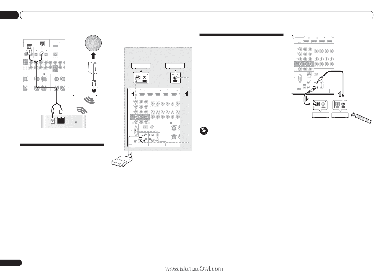
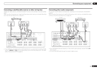
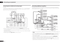
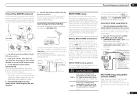
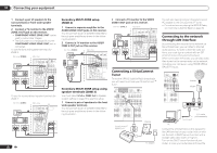
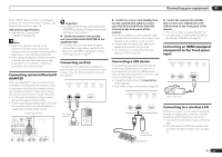
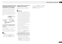
03 Connecting your equipment DC OUTPUT 2 forWIRELESS LAN (OUTPUT 5 V 0.6 A MAX) LAN (10/100) L ASSIGNABLE OPTICAL ASSIGNABLE IN 1 IN 2 IN 1 IN 2 IN 3 (DVD) (CD) (TV/SAT) (DVR/BDR) (VIDEO) ADAPTER PORT (OUTPUT 5 V 0.1 A MAX) OUT OOFER 2 SURROUND SURR BACK F HEIGHT (Single) F WIDE FRONT CENTER SURROUND SURR GHT L PRE OUT FRONTWIDE / B R L SUBWOOFER MULTI SURROUND R Internet Modem Router WAN DC 5V Ethernet WPS Wireless LAN converter (AS-WL300) Connecting an IR receiver If you keep your stereo components in a closed cabinet or shelving unit, or you wish to use the sub zone remote control in another zone, you can use an optional IR receiver (such as a Niles or Xantech unit) to control your system instead of the remote sensor on the front panel of this receiver. ! Remote operation may not be possible if direct light from a strong fluorescent lamp is shining on the IR receiver remote sensor window. ! Note that other manufacturers may not use the IR terminology. Refer to the manual that came with your component to check for IR compatibility. ! If using two remote controls (at the same time), the IR receiver's remote sensor takes priority over the remote sensor on the front panel. 1 Connect the IR receiver sensor to the IR IN jack on the rear of this receiver. Closet or shelving unit Pioneer component Non-Pioneer component CONTROL IR IN OUT IN IN 1 IN 2 HDMI ASSIGNABLE 16 ASSIGNABLE Y COMPONENT VIDEO PB PR IN 1 (DVD) IN 4 (VIDEO) BD IN IN 5 (DVD) IN 2 (DVR/ BDR) IN 3 (VIDEO) MONITOR OUT ZONE 2 ZONE 3 DVD TV/SAT VIDEO DVR/ OUT OUT IN IN IN OUT ZONE2 OUT RS-232C A FRONT R AM LOOP ANTENNA FM UNBAL 75 IR IN 1 IN 1 SPEAKERS OUT IN 2 OUT 2 (OUTPUT 12 V (OUTPUT 5 V TOTAL 150 mA MAX) EXTENSION 150 mA MAX) CONTROL 12VTRIGGER IR receiver 2 Connect the IR IN jack of another component to the IR OUT jack on the rear of this receiver to link it to the IR receiver. Please see the manual supplied with your IR receiver for the type of cable necessary for the connection. ! If you want to link a Pioneer component to the IR receiver, see Operating other Pioneer components with this unit's sensor on page 30 to connect to the CONTROL jacks instead of the IR OUT jack. Operating other Pioneer components with this unit's sensor Many Pioneer components have SR CONTROL jacks which can be used to link components together so that you can use just the remote sensor of one component. When you use a remote control, the control signal is passed along the chain to the appropriate component. ! If you want to control all your components using this receiver's remote control, see page 63. ! If you have connected a remote control to the CONTROL IN jack (using a mini-plug cable), you won't be able to control this unit using the remote sensor. Important ! Note that if you use this feature, make sure that you also have at least one set of analog audio, video or HDMI jacks connected to another component for grounding purposes. 1 Decide which component you want to use the remote sensor of. When you want to control any component in the chain, this is the remote sensor at which you'll point the corresponding remote control. 2 Connect the CONTROL OUT jack of that component to the CONTROL IN jack of another Pioneer component. Use a cable with a mono mini-plug on each end for the connection. IN 1 IN 2 HDMI ASSIGNABLE 16 ASSIGNABLE Y COMPONENT VIDEO PB PR IN 1 (DVD) IN 4 (VIDEO) BD IN IN 2 (DVR/ BDR) IN 3 (VIDEO) MONITOR OUT ZONE 2 ZONE 3 DVD TV/SAT OUT OUT IN IN ZONE2 OUT RS-232C AM LOOP ANTENNA FM UNBAL 75 IR IN 1 IN 1 SPEAKERS OUT IN 2 OUT 2 (OUTPUT 12 V (OUTPUT 5 V TOTAL 150 mA MAX) EXTENSION 150 mA MAX) CONTROL 12VTRIGGER IN OUT CONTROL IN OUT CONTROL 3 Continue the chain in the same way for as many components as you have. 30 En
-
 1
1 -
2
-
3
-
4
-
5
-
6
-
7
-
8
-
9
-
10
-
11
-
12
-
13
-
14
-
15
-
16
-
17
-
18
-
19
-
20
-
21
-
22
-
23
-
24
-
 25
25 -
 26
26 -
 27
27 -
 28
28 -
 29
29 -
 30
30 -
 31
31 -
 32
32 -
 33
33 -
 34
34 -
 35
35 -
36
-
37
-
38
-
39
-
40
-
41
-
42
-
43
-
44
-
45
-
46
-
47
-
48
-
49
-
50
-
51
-
52
-
53
-
54
-
55
-
56
-
57
-
58
-
59
-
60
-
61
-
62
-
63
-
64
-
65
-
66
-
67
-
68
-
69
-
70
-
71
-
72
-
73
-
74
-
75
-
76
-
77
-
78
-
79
-
80
-
81
-
82
-
83
-
84
-
85
-
86
-
87
-
88
-
89
-
90
-
91
-
92
-
93
-
94
-
95
-
96
-
97
-
98
-
99
-
100
-
101
-
102
-
103
-
104
-
105
-
106
-
107
-
108
 |
 |