Pioneer SDV-P7 Other Manual
Pioneer SDV-P7 - DVD Player - in-dash Manual
 |
View all Pioneer SDV-P7 manuals
Add to My Manuals
Save this manual to your list of manuals |
Pioneer SDV-P7 manual content summary:
- Pioneer SDV-P7 | Other Manual - Page 1
beginning installation. • Refer to the owner's manual for details on connecting the power amp and other units, then make connections correctly. • Secure the wiring with cable clamps or adhesive tape. To protect the wiring, wrap adhesive tape around them where they lie against metal parts. • Route - Pioneer SDV-P7 | Other Manual - Page 2
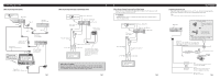
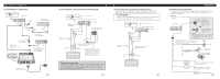
To audio inputs Display with RCA input jacks This product features a built-in remote sensor. If it is installed in a location where reception of the remote control signal is not possible, use a separately sold remote sensor. Connecting a rear display Instead of video output for viewing on a front - Pioneer SDV-P7 | Other Manual - Page 3
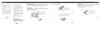
wiring or other important parts. • If this unit is installed in the passenger compartment, anchor it securely so it does not break free while the car is unit, pull the unit out. Fig. 9 Fig. 10 DIN Rear-mount Installation using the screw holes on the side of the unit 1. Remove the frame. - Pioneer SDV-P7 | Other Manual - Page 4
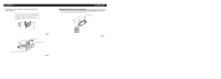
Installation 2. Fastening the unit to the factory radio mounting bracket. (Fig. 12) (Fig. 13) Select a position where the screw holes of the bracket and the screw holes of this unit become aligned (are fitted), and tighten the screws at 2 places on each side. Use either truss screws (5 × 8 mm) or - Pioneer SDV-P7 | Other Manual - Page 5
: • Cet appareil est destiné aux véhicules avec une bat- terie de 12 V, avec pôle négatif à la masse. Avant de l'installer dans un véhicule de loisir, un camion ou un car, vérifier la tension de la batterie. • Afin d'éviter tout risque de court-circuit, débrancher le câble de la borne négative ≠ de - Pioneer SDV-P7 | Other Manual - Page 6
que les passagers arrière puissent regarder les images fournies par un DVD ou un Video CD. AVERTISSEMENT • Veillez à ce que l'écran NE SOIT PAS installé en un endroit tel que le conducteur puisse observer les images fournies par le DVD ou le Video CD tout en conduisant. IP-BUS Blanc (sortie audio - Pioneer SDV-P7 | Other Manual - Page 7
portières car il pourrait être éclaboussé par la pluie ou les intempéries. • Avant d'effectuer un perçage requis par l'installation de l'appareil Montage DIN avant Installation avec une bague en caoutchouc (Fig. 8) Tableau de bord 182 53 Support Après avoir introduit le support dans le tableau - Pioneer SDV-P7 | Other Manual - Page 8
Fixation de l'appareil au support pour le montage de la radio installée par le constructeur. (Fig. 12) (Fig. 13) Choisir la position selon laquelle les orifices de vis du support et ceux des vis de cette appareil sont alignés (correspondent) et serrer les vis sur 2 endroits de chaque côté. Utiliser
-
 1
1 -
 2
2 -
 3
3 -
 4
4 -
 5
5 -
 6
6 -
 7
7 -
8
 |
 |
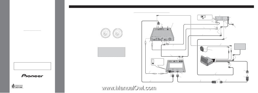
INSTALLATION MANUAL
MANUEL D’INSTALLATION
<KYMFF/01D00000>
SDV-P7
Printed in Japan
Imprimé au Japon
<CRD3465-A> UC
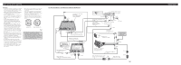
Connecting the Units
<ENGLISH>
Note:
•
This unit is for vehicles with a 12-volt battery and
negative grounding. Before installing it in a recre-
ational vehicle, truck, or bus, check the battery
voltage.
•
To avoid shorts in the electrical system, be sure to
disconnect the
≠
battery cable before beginning
installation.
•
Refer to the owner
’
s manual for details on
connecting the power amp and other units, then
make connections correctly.
•
Secure the wiring with cable clamps or adhesive
tape. To protect the wiring, wrap adhesive tape
around them where they lie against metal parts.
•
Route and secure all wiring so it cannot touch any
moving parts, such as the gear shift, handbrake and
seat rails. Do not route wiring in places that get
hot, such as near the heater outlet. If the insulation
of the wiring melts or gets torn, there is a danger of
the wiring short-circuiting to the vehicle body.
•
Don
’
t pass the yellow lead through a hole into the
engine compartment to connect to the battery. This
will damage the lead insulation and cause a very
dangerous short.
•
Do not shorten any leads. If you do, the protection
circuit may fail to work when it should.
•
Never feed power to other equipment by cutting
the insulation of the power supply lead of the unit
and tapping into the lead. The current capacity of
the lead will be exceeded, causing overheating.
•
When replacing fuse, be sure to use only fuse of
the rating prescribed on the fuse holder.
•
To prevent incorrect connection, the input side of
the IP-BUS connector is blue, and the output side
is black. Connect the connectors of the same
colors correctly.
•
If this unit is installed in a vehicle that does not
have an ACC (accessory) position on the ignition
switch, the red lead of the unit should be connected
to a terminal coupled with ignition switch ON/OFF
operations. If this is not done, the vehicle battery
may be drained when you are away from the vehi-
cle for several hours. (Fig.1)
Fig. 1
No ACC position
ACC position
O
N
S
T
A
R
T
O
F
F
A
C
C
O
N
S
T
A
R
T
O
F
F
This product conforms to CEMA cord colors.
Le code de couleur des c
â
bles utilis
é
pour ce produit est
conforme
à
CEMA.
•
Cords for this product and those for other products
may be different colors even if they have the same
function. When connecting this product to another
product, refer to the supplied Installation manuals
of both products and connect cords that have the
same function.
Hide-away TV Tuner
(e.g. GEX-P7000TV)
(sold separately)
Multi-CD player
(sold separately)
Green
Gray
AV cable (supplied with the
Multi-Channel AV Master Unit)
V.SEL cable
(supplied with the display)
RCA cable (supplied)
RCA cable
(sold separately)
Blue
Yellow
IP-BUS cable
(supplied with the Multi-
Channel AV Master Unit)
Optical cable (supplied with the
Multi-Channel AV Master Unit)
Speaker Unit
(supplied with the
display)
20 pin cable
(supplied with the TV tuner)
IP-BUS cable
(supplied with the display)
IP-BUS cable
(supplied with the TV tuner)
Blue
Blue
Blue
Black
Black
AV system Display
(e.g. AVX-P7000CD)
(sold separately)
Red
Green
Gray
Gray
Green
20 pin cable
(supplied with the display)
FM MODULATOR
IP-BUS MAIN UNIT
IP-BUS AV MASTER
Blue
STAND ALONE
IP-BUS
15 cm
40 cm
Yellow
Blue
Blue
Multi-Channel AV
Master Unit (e.g. AVM-P9000R)
(sold separately)
Not used.
This product
6m
Yellow (front video output)
Black
Fig. 2
When Connecting the Multi-Channel AV Master Unit