Pioneer SVM 1000 SVM-1000 Operating Instructions - Page 12
Connecting Microphone And Headphones, Connecting The Power Cord - used
 |
UPC - 012562870540
View all Pioneer SVM 1000 manuals
Add to My Manuals
Save this manual to your list of manuals |
Page 12 highlights
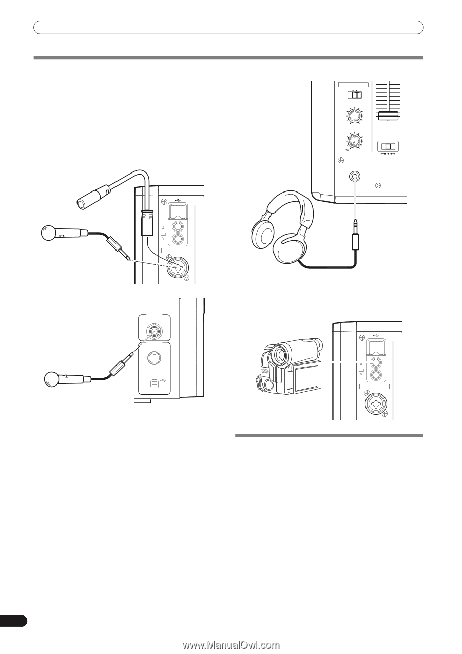
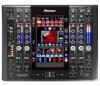
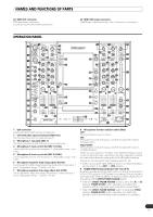
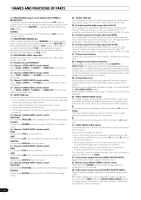
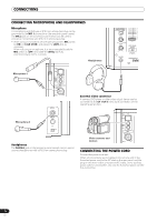
CONNECTIONS CONNECTING MICROPHONE AND HEADPHONES Microphone A microphone with XLR-type or Ø 6.3 mm phone-type plug can be connected to the MIC 1 connector on the operation panel (upper) . The MIC 2 jack on the connection panel (rear) can be used to connect a microphone with Ø 6.3 mm phone-type plug. • When using a microphone, set the operating panel's MIC switch to [ON] or [TALK OVER], and adjust the LEVEL dial as necessary. When not using a microphone, it is recommended to set the MIC switch to [OFF] and rotate the LEVEL dial fully counterclockwise to the [-∞] side. Headphones HEAD PHONES MONO SPLIT STEREO MIXING CUE MASTER LEVEL 9 8 7 6 5 4 3 2 1 0 CROSS FADER ASSIGN 0 PHONES A THRU B PROFESSIONAL SO SVM- Microphone 1 USB CH 1 VIDEO EX CH 4 MIC MIC 1 MIC2 External video connector A camera, DVD player or other video output device can be connected to the CH 1/CH 4 video input connectors on the operating panel (top). Microphone 2 MIDI OUT USB Headphones The PHONES jack on the operating panel (upper) can be used to connect headphones with a Ø 6.3 mm stereo phone plug. Video cameras and devices USB CH 1 VIDEO EX CH 4 MIC MIC 1 CONNECTING THE POWER CORD Connect the power cord last. When all connections are completed, connect one end of the furnished power cord to the AC inlet on the rear panel, and the plug on the other end to a household AC outlet, or the auxiliary power outlet on an amplifier. Use only the furnished power cord for this connection. 12 En
-
 1
1 -
2
-
3
-
4
-
5
-
6
-
 7
7 -
 8
8 -
 9
9 -
 10
10 -
 11
11 -
 12
12 -
 13
13 -
 14
14 -
 15
15 -
 16
16 -
 17
17 -
18
-
19
-
20
-
21
-
22
-
23
-
24
-
25
-
26
-
27
-
28
-
29
-
30
-
31
-
32
-
33
-
34
-
35
-
36
-
37
-
38
-
39
-
40
-
41
-
42
-
43
-
44
-
45
-
46
-
47
-
48
 |
 |