Pioneer SVM 1000 SVM-1000 Operating Instructions - Page 6
Names And Functions Of Parts - vjs
 |
UPC - 012562870540
View all Pioneer SVM 1000 manuals
Add to My Manuals
Save this manual to your list of manuals |
Page 6 highlights
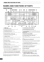
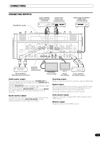
NAMES AND FUNCTIONS OF PARTS NAMES AND FUNCTIONS OF PARTS CONNECTION PANEL 1 2 34 5 6 7 5 89 10 11 12 6 7 5 2 3 4 5 13 POWER 4 3 SIGNAL GND PHONO DVD/LINE LINE DVD L R OFF ON L CONTROL R SYNC OUT DIGITAL IN CONTROL SYNC OUT AUDIO OUT 1 GND 2 HOT MASTER OUT 1 R L 3 COLD MASTER REC OUT 2 OUT MASTER L ATT. -3 dB -6 dB 0 dB R BOOTH MONITOR (TRS) R L 2 LINE L R 1 SIGNAL GND DVD PHONO DVD/LINE L CONTROL R CONTROL 14 15 16 DIGITAL OUT fs (Hz) 48 k 96 k 17 15 DIGITAL IN SYNC OUT SYNC OUT 14 AC IN S-VIDEO DVD S-VIDEO DVD VIDEO OUT MASTER COMPONENT Y CB CR COMPOSITE MONITOR S-VIDEO DVD S-VIDEO DVD MIC2 MIDI OUT USB VIDEO VIDEO S-VIDEO S-VIDEO VIDEO VIDEO 18 19 19 20 21 19 19 22 23 1 POWER switch 2 PHONO input connectors RCA type phono level (MM cartridge) input connectors. Do not use for inputting line level signals. 3 DVD/LINE input connectors RCA type line level audio input connectors. Use to connect a DJ/VJ DVD player or DJ CD player or other line level output component. 4 Signal ground terminal (SIGNAL GND) Connect the ground wire from an analog turntable. This is not a safety ground terminal. 5 CONTROL connector Connect the Ø 3.5 mm mini phone plug of the control cable from a DJ/VJ DVD player or DJ CD player. When this is done, this mixer's fader controls can be used to perform start and back-cue functions on the connected DJ/VJ DVD player or DJ CD player. 6 LINE input connectors RCA type line level audio input connectors. Use to connect a cassette deck or other line level output component. 7 DVD input connectors RCA type line level audio input connectors. Use to connect a DJ/VJ DVD player or DJ CD player or other line level output component. 8 Audio master output 1 connectors (MASTER OUT 1) XLR type (male) balanced output. • When using a cord with RCA-type plug, users are recommended to connect the plug directly to the MASTER OUT 2 connectors without using an XLR/RCA converter plug. When a conversion plug is used, the signal GND may become unstable, in rare cases resulting in the production of noise. 9 Audio master output attenuator selector (MASTER ATT.) Attenuates the output level of the audio master 1 and audio master 2. Attenuation level can be selected as 0 dB, -3 dB, or -6 dB. 10 Audio master output 2 connectors (MASTER OUT 2) RCA-type unbalanced output. 11 Recording output connectors (REC OUT) RCA type output connectors for recording. 12 BOOTH MONITOR output jacks (TRS) Ø 6.3 mm phone-type booth monitor output jacks. The sound level output at these connectors can be controlled by the BOOTH MONITOR level dial, regardless of the setting of the MASTER LEVEL dial. (Since the output is TRS, both balanced and unbalanced outputs are supported.) 13 Microphone 2 input jack (MIC 2) Connect microphones equipped with phone-type plug. 14 Sync signal output connector (SYNC OUT) Outputs video sync signal. When connecting a Pioneer DJ/VJ DVD player (sold separately), the sync signal helps suppress any lag between video and audio signals. 15 Digital input connector (DIGITAL IN) RCA-type digital coaxial input connector. Connect to the digital coaxial output connector from a DJ/VJ DVD player or DJ CD player. • If the sampling frequency of the output signal changes, the sound may be interrupted briefly. 16 Sampling frequency selector switch (fs 48 k/96 k) Use to set the sampling frequency of the digital output to 96 kHz/ 24-bit format or 48 kHz/24-bit format. Turn power off before changing this switch position. 17 Digital output connector (DIGITAL OUT) RCA type digital coaxial output connector. Master audio digital output. 18 Power inlet (AC IN) Use the furnished power cable to connect to a household AC outlet. 19 Video input connectors (DVD, VIDEO, S-VIDEO) Composite and S-VIDEO type video input connectors. 20 Video master output connectors (MASTER: COMPONENT, COMPOSITE, S-VIDEO) Component, composite, and S-VIDEO type video output connectors. 21 Video monitor output connectors (MONITOR, S-VIDEO) Composite and S-VIDEO type monitor video output connectors. 6 En
-
 1
1 -
 2
2 -
 3
3 -
 4
4 -
 5
5 -
 6
6 -
 7
7 -
 8
8 -
 9
9 -
 10
10 -
 11
11 -
 12
12 -
13
-
14
-
15
-
16
-
17
-
18
-
19
-
20
-
21
-
22
-
23
-
24
-
25
-
26
-
27
-
28
-
29
-
30
-
31
-
32
-
33
-
34
-
35
-
36
-
37
-
38
-
39
-
40
-
41
-
42
-
43
-
44
-
45
-
46
-
47
-
48
 |
 |
