Pioneer SVM 1000 SVM-1000 Operating Instructions - Page 7
Operation Panel - professional audio video mixer
 |
UPC - 012562870540
View all Pioneer SVM 1000 manuals
Add to My Manuals
Save this manual to your list of manuals |
Page 7 highlights
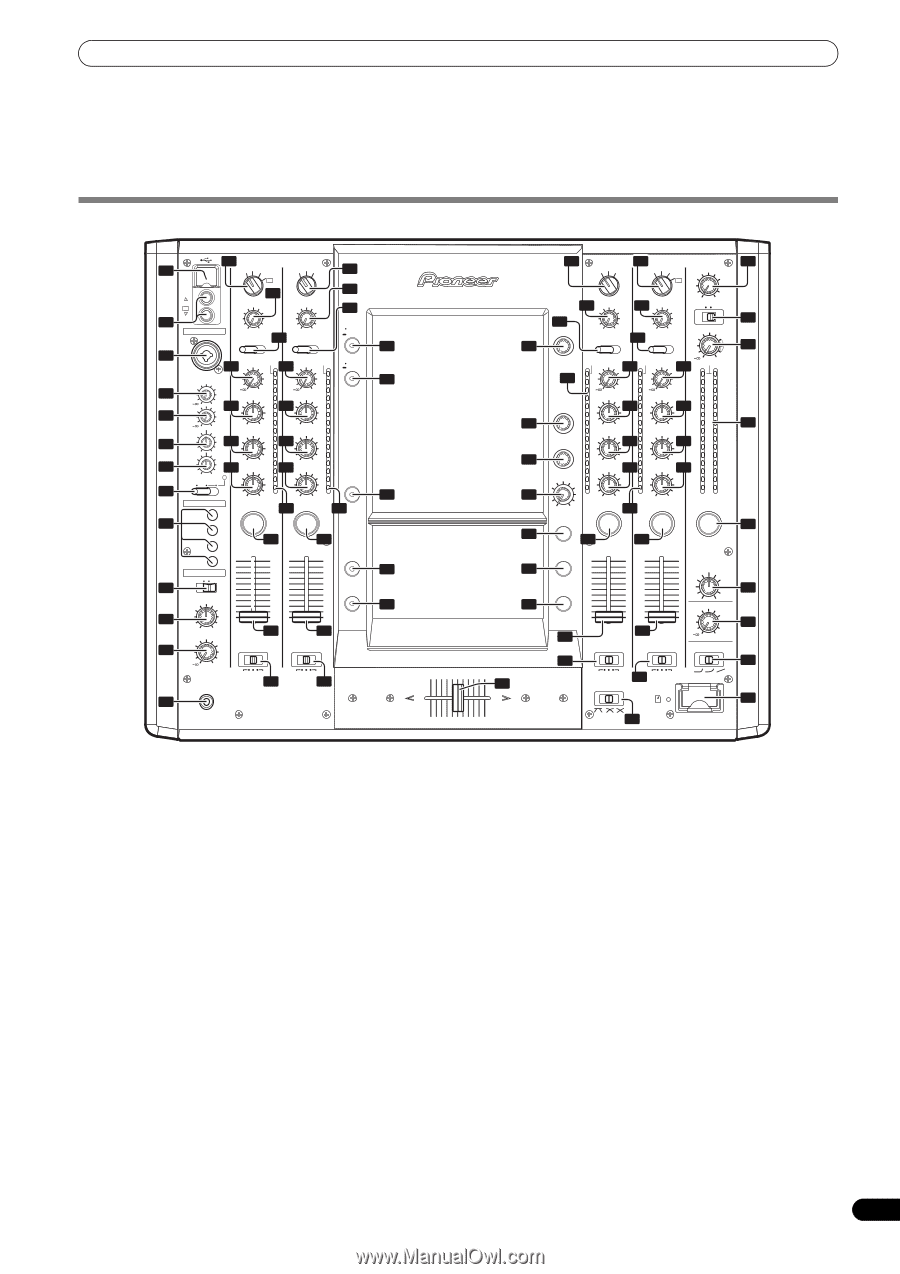
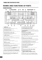
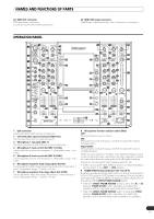
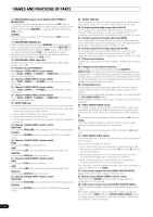
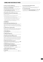
NAMES AND FUNCTIONS OF PARTS 22 MIDI OUT connector DIN type output connector. Use to connect to other MIDI component. 23 MIDI USB output connector USB-B type output connector. Use to connect to a computer. OPERATION PANEL 1 USB CH 1 VIDEO EX 2 CH 4 MIC 14 VIDEO INPUT DVD VIDEO S-VIDEO VIDEO EX 18 VIDEO TRIM VIDEO INPUT DVD VIDEO S-VIDEO VIDEO TRIM MIN MAX MIN MAX 19 AUDIO INPUT AUDIO INPUT DVD/LINE PHONO DVD LINE DIGITAL 15 18 20 UTILITY MASTER MONITOR SET UP 3 4 5 6 7 8 9 10 11 12 MIC 1 23 23 AUDIO TRIM OVER AUDIO TRIM OVER VIDEO EQ ON/OFF SET UP MIC1 LEVEL MIC2 LEVEL 0 24 10 +9 7 HI 4 2 1 HI -12 LOW -12 0 0 -26 +6 MID -1 25 -2 -3 +12 -5 26 -26 +6 -7 LOW -10 +12 TALK -15 MIC OFF ON OVER -24 10 24 +9 7 HI 4 2 1 0 -26 +6 MID -1 25 -2 -3 -5 26 -26 +6 -7 LOW -10 -15 -24 JPEG VIEWER FADER START CH1 CH2 CH3 CH4 HEAD PHONES MONO SPLIT STEREO MIXING -26 +6 dB -26 +6 dB 27 27 CUE CUE 1 28 2 28 VIDEO SOLO MODE 10 10 9 9 8 8 7 7 6 6 5 5 FADER AV SYNC 4 4 3 3 2 2 1 1 0 0 CUE MASTER LEVEL 29 CROSS FADER ASSIGN 29 CROSS FADER ASSIGN 40 41 42 43 44 0 PHONES A THRU B 30 A THRU B 30 13 PROFESSIONAL SOUND&VISION MIXER SVM-1000 A 16 VIDEO INPUT 17 VIDEO INPUT DVD VIDEO S-VIDEO DVD VIDEO S-VIDEO VIDEO EX VIDEO MASTER LEVEL 32 51 45 46 47 48 28 18 VIDEO TRIM 18 VIDEO TRIM 21 CH SELECT MIN MAX MIN MAX 22 AUDIO INPUT AUDIO INPUT DVD LINE DIGITAL LINE PHONO BLACK WHITE MONO STEREO 33 AUDIO MASTER LEVEL 34 27 VIDEO FX PATTERN/ TEXT BANK TIME/ PARAMETER LEVEL/ DEPTH 23 23 OVER AUDIO TRIM OVER AUDIO TRIM 10 7 +9 4 HI 2 24 1 0 -26 +6 -1 MID -2 25 -3 -5 26 -7 -26 +6 LOW -10 -15 -24 10 7 +9 4 HI 2 24 1 0 -26 +6 -1 MID -2 25 -3 -5 26 -7 -26 +6 LOW -10 -15 -24 MIN MAX EFFECT CUE dB -26 +6 dB -26 +6 27 CUE CUE 0 OVER 10 7 4 2 1 0 -1 -2 -3 -5 -7 -10 -15 -24 L dB R CUE 3 4 28 28 MASTER 35 28 49 50 EFFECT ON/OFF 29 30 10 9 8 7 6 5 4 3 2 1 0 CROSS FADER ASSIGN 10 9 8 7 6 5 4 3 2 1 0 29 CROSS FADER ASSIGN BALANCE L R BOOTH MONITOR 0 CH FADER CURVE 36 37 38 A THRU B 30 A THRU B CROSS FADER CURVE SD CARD B 39 31 1 USB connector Use to connect a USB memory or keyboard. 2 CH1/CH4 video input connectors (VIDEO EX) Use to input video from an external source. 3 Microphone 1 input jack (MIC 1) Connect microphone with XLR-type or phone-type plug. 4 Microphone 1 level control dial (MIC 1 LEVEL) Use to adjust the volume of microphone 1. (Adjustable range -∞ to 0 dB) 5 Microphone 2 level control dial (MIC 2 LEVEL) Use to adjust the volume of microphone 2. (Adjustable range -∞ to 0 dB) 6 Microphone equalizer high-range adjust dial (HI) Use to adjust the treble (high-range) frequencies of microphones 1 and 2. (Adjustable range -12 dB to +12 dB) 7 Microphone equalizer low-range adjust dial (LOW) Use to adjust the bass (low-range) frequencies of microphones 1 and 2. (Adjustable range -12 dB to +12 dB) 8 Microphone function selector switch (MIC) OFF: No microphone sound is output. ON: Microphone sounds are output, and the microphone function indicator lights. TALK OVER: Microphone sounds are output, and the microphone function indicator flashes. When an audio signal of -15 dB or more (default setting) is input to the microphone input, the talkover function operates to reduce all output other than the mike audio by 20 dB (default setting). Values can be changed in the hardware setup (P. 42) • When not using the TALK OVER function, it is recommended to set the switch to the [OFF] or [ON] position. 9 FADER START button/indicator (CH-1 to CH-4) Enables the fader start/back cue function for the channel to which a DJ/VJ DVD player or DJ CD player is connected. The button lights when set to ON. When enabled, the operation differs depending on the setting of the CROSS FADER ASSIGN switch. • When the CROSS FADER ASSIGN switch is set to the [A] or [B] position, FADER START button operation is linked to the operation of the cross fader (and unlinked to channel fader). • When the CROSS FADER ASSIGN switch is set to the [THRU] position, FADER START button operation is linked to the operation of the channel fader (and unlinked to cross fader). 7 En
-
 1
1 -
 2
2 -
 3
3 -
 4
4 -
 5
5 -
 6
6 -
 7
7 -
 8
8 -
 9
9 -
 10
10 -
 11
11 -
 12
12 -
13
-
14
-
15
-
16
-
17
-
18
-
19
-
20
-
21
-
22
-
23
-
24
-
25
-
26
-
27
-
28
-
29
-
30
-
31
-
32
-
33
-
34
-
35
-
36
-
37
-
38
-
39
-
40
-
41
-
42
-
43
-
44
-
45
-
46
-
47
-
48
 |
 |