Pioneer VSX-43 Owner's Manual - Page 16
About video outputs connection - 4k
 |
View all Pioneer VSX-43 manuals
Add to My Manuals
Save this manual to your list of manuals |
Page 16 highlights
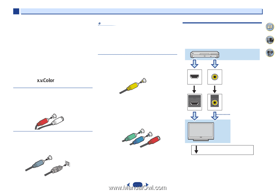
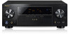
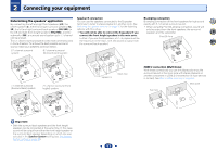
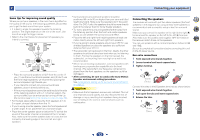
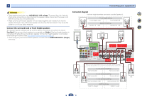
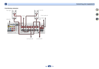
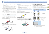
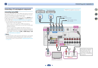
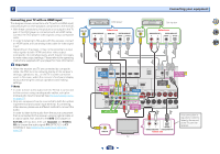
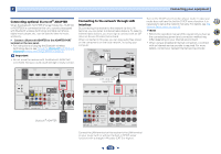
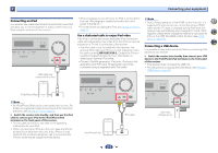
2 Connecting your equipment • 3D, Deep Color, x.v.Color, 4K signal transfer and Audio Return Channel are only possible when connected to a compatible component. • HDMI format digital audio transmissions require a longer time to be recognized. Due to this, interruption in the audio may occur when switching between audio formats or beginning playback. • Turning on/off the device connected to this unit's HDMI OUT terminal during playback, or disconnecting/ connecting the HDMI cable during playback, may cause noise or interrupted audio. The terms HDMI and HDMI High-Definition Multimedia Interface, and the HDMI Logo are trademarks or registered trademarks of HDMI Licensing, LLC in the United States and other countries. "x.v.Color" and Corporation. are trademarks of Sony Analog audio cables Use stereo RCA phono cables to connect analog audio components. These cables are typically red and white, and you should connect the red plugs to R (right) terminals and white plugs to L (left) terminals. Red (Right) R L AUDIO White (Left) Digital audio cables Commercially available coaxial digital audio cables or optical cables should be used to connect digital components to this receiver. Coaxial digital audio cable COAINXIAL OPTINICAL Note • When connecting optical cables, be careful when inserting the plug not to damage the shutter protecting the optical socket. • When storing optical cable, coil loosely. The cable may be damaged if bent around sharp corners. • You can also use a standard RCA video cable for coaxial digital connections. Video cables Standard RCA video cables These cables are the most common type of video connection and are used to connect to the composite video terminals. The yellow plugs distinguish them from cables for audio. Yellow VIDEO Component video cables Use component video cables to get the best possible color reproduction of your video source. The color signal of the TV is divided into the luminance (Y) signal and the color (PB and PR) signals and then output. In this way, interference between the signals is avoided. Green (Y) CYOMPONENT PB VIDEO PR Blue (PB) Red (PR) About video outputs connection This receiver is not loaded with a video converter. When you use HDMI cables for connecting to the input device, the same cables should be used for connecting to the TV. The signals input from the analog (composite) video inputs of this unit will not be output from the HDMI OUT terminal. Playback component 4 7 62 IN HDMI OUT HDMI IN VIDEO Terminal for connection with source device MONITOR OUT VIDEO Terminal for connection with TV monitor The OSD will not appear. TV Video signals can be output. Optical cable 16
-
 1
1 -
2
-
3
-
4
-
5
-
6
-
7
-
8
-
9
-
10
-
 11
11 -
 12
12 -
 13
13 -
 14
14 -
 15
15 -
 16
16 -
 17
17 -
 18
18 -
 19
19 -
 20
20 -
 21
21 -
22
-
23
-
24
-
25
-
26
-
27
-
28
-
29
-
30
-
31
-
32
-
33
-
34
-
35
-
36
-
37
-
38
-
39
-
40
-
41
-
42
-
43
-
44
-
45
-
46
-
47
-
48
-
49
-
50
-
51
-
52
-
53
-
54
-
55
-
56
-
57
-
58
-
59
-
60
-
61
-
62
-
63
-
64
-
65
-
66
-
67
-
68
 |
 |