Pioneer VSX-521-K Owner's Manual - Page 32
Select 'Speaker Distance' from the Manual SP Setup - audio return channel
 |
UPC - 884938133043
View all Pioneer VSX-521-K manuals
Add to My Manuals
Save this manual to your list of manuals |
Page 32 highlights
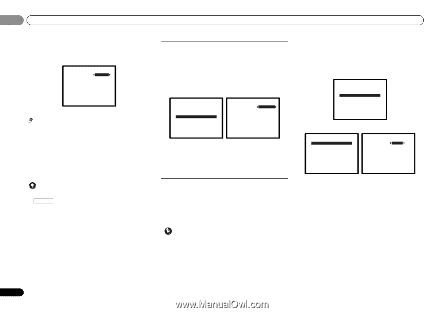
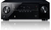
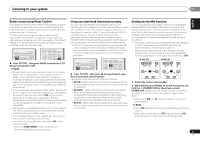
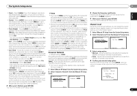
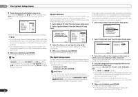
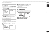
06 The System Setup menu 5 Adjust the level of each channel using /. If you selected Manual, use / to switch speakers. The Auto setup will output test tones in the order shown onscreen: 2c.Channel Level Front L Center [ Front R [ Surround R [ Surr. Back R [ Surr. Back L [ Surround L [ Subwoofer [ 0dB 0dB] 0dB] 0dB 0dB] 0dB] Return Adjust the level of each speaker as the test tone is emitted. Note • If you are using a Sound Pressure Level (SPL) meter, take the readings from your main listening position and adjust the level of each speaker to 75 dB SPL (C-weighting/slow reading). • The subwoofer test tone is output at low volumes. You may need to adjust the level after testing with an actual soundtrack. 6 When you're finished, press RETURN. You return to the Manual SP Setup menu. Tip • You can change the channel levels at any time by press RECEIVER , then press CH SELECT and LEV +/- on the remote control. You can also press CH SELECT and use / to select the channel, and then use / to adjust the channel levels. 32 En Speaker Distance For good sound depth and separation from your system, you need to specify the distance of your speakers from the listening position. The receiver can then add the proper delay needed for effective surround sound. 1 Select 'Manual SP Setup' from the System Setup menu. 2 Select 'Speaker Distance' from the Manual SP Setup menu. 2.Manual SP Setup a.Speaker Setting b.Crossover Network c.Channel Level d.Speaker Distance Return 2d.Speaker Distance Front L Center Front R Surround R Surr. Back R Surr. Back L Surround L Subwoofer 10.0 ft [ 10.0 ft ] [ 10.0 tt ] [ 10.0 ft ] [ ---- ] [ ---- ] [ 10.0 ft ] [ 10.0 ft ] Return 3 Adjust the distance of each speaker using /. You can adjust the distance of each speaker in 0.1 feet increments. 4 When you're finished, press RETURN. You return to the Manual SP Setup menu. The Input Assign menu You only need to make settings in the Input Assign menu if you didn't hook up your equipment according to the default settings for the component video inputs. • Default settings: - Component-1: DVD - Component-2: DVR (DVR/BDR) Important • If you connect any source component to the receiver using a component video input, you should also have your TV connected to this receiver's COMPONENT VIDEO MONITOR OUT output (down converting component video is not possible after assigning an input). If you didn't make component video connections according to the defaults above, you must assign the numbered input to the component you've connected (or else you may see the video signal of a different component). For more on this, see Using the component video jacks on page 16. 1 Select 'Input Assign' from the System Setup menu. System Setup 1 . Auto MCACC 2 . Manual SP Setup 3 . Input Assign 4 . Pre Out Setting 5 . HDMI Setup 6 . Auto Power Down 7 . FL Demo Mode Return 2 Select 'Component Input' from the Input Assign menu. 3.Input Assign a.Component Input 3a.Component Input Component-1 DVD Component-2 [ DVR ] Return Return 3 Select the number of the component video input to which you've connected your video component. The numbers correspond with the numbers beside the inputs on the rear of the receiver. 4 Select the component that corresponds with the one you connected to that input. Select between BD, DVD, TV (TV/SAT), DVR (DVR/BDR) or OFF. • Use / and ENTER to do this. • If you assign a component input to a certain function, any component inputs previously assigned to that function will automatically be switched off. • Make sure you have connected the audio from the component to the corresponding inputs on the rear of the receiver. 5 When you're finished, press RETURN. You return to the Input Assign menu. • For the assignment of the digital signal inputs, see Selecting the audio input signal on page 21.
-
 1
1 -
2
-
3
-
4
-
5
-
6
-
7
-
8
-
9
-
10
-
11
-
12
-
13
-
14
-
15
-
16
-
17
-
18
-
19
-
20
-
21
-
22
-
23
-
24
-
25
-
26
-
 27
27 -
 28
28 -
 29
29 -
 30
30 -
 31
31 -
 32
32 -
 33
33 -
 34
34 -
 35
35 -
 36
36 -
 37
37 -
38
-
39
-
40
-
41
-
42
-
43
-
44
-
45
-
46
-
47
-
48
-
49
-
50
-
51
-
52
-
53
-
54
-
55
-
56
-
57
-
58
-
59
-
60
-
61
-
62
-
63
-
64
-
65
-
66
-
67
-
68
-
69
-
70
-
71
-
72
-
73
-
74
-
75
-
76
-
77
-
78
-
79
-
80
-
81
-
82
-
83
-
84
-
85
-
86
-
87
-
88
-
89
-
90
-
91
-
92
-
93
-
94
-
95
-
96
-
97
-
98
-
99
-
100
-
101
-
102
-
103
-
104
-
105
-
106
-
107
-
108
-
109
-
110
-
111
-
112
-
113
-
114
-
115
-
116
-
117
-
118
-
119
-
120
 |
 |