Polaroid 4011-TLXB Service Manual
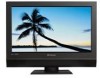
Polaroid 4011-TLXB - 40" LCD TV Manual
 |
UPC - 826219010049
View all Polaroid 4011-TLXB manuals
Add to My Manuals
Save this manual to your list of manuals |
Polaroid 4011-TLXB manual content summary:
- Polaroid 4011-TLXB | Service Manual - Page 1
2007 LCD Models - North America TLA-04011C, TLXB-4011, TLXB-4241 SERVICE MANUAL Bezel covers vary by model 20070613 - Polaroid 4011-TLXB | Service Manual - Page 2
service manual, please ensure that you have carefully followed all the procedures outlined in the user's manual for this product. (1) Read all of these instructions. (2) Save these instructions. (3) Follow all warnings and instructions power cord. Do not locate this product where people will parts that - Polaroid 4011-TLXB | Service Manual - Page 3
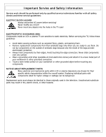
HAZARD Always disconnect AC power before servicing! Never modify any circuit! Never insert any objects into the holes in the TV case! ELECTROSTATIC DISCHARGE (ESD) Components inside an LCD or plasma TV are sensitive to static electricity. Before servicing the TV, follow these guidelines: • Avoid - Polaroid 4011-TLXB | Service Manual - Page 4
Service and Safety Information PRECAUTIONS FOR USING LEAD-FREE SOLDER Components within this television use lead-free solder (Sn-Ag-Cu). Whenever soldering, look at the markings on boards and components within the television When repairing components joints will no with parts for bit powered on for - Polaroid 4011-TLXB | Service Manual - Page 5
10 3. Troubleshooting / Flow Charts ...16 Factory Mode Procedure...16 4. Polaroid Display Cell Defect Specification 20 5. Before Returning This Product to the User 21 6. Disassembly Procedure...22 Stand and Control Box Removal 23 Rear Cabinet Cover, LCD Panel and Front Bezel 25 IR Board Removal - Polaroid 4011-TLXB | Service Manual - Page 6
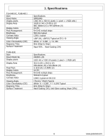
TLXB-4011 Item Panel Name Display pixels Display Area Display Colors Pixel Arrangement Brightness Contrast Ratio Viewing Angle Color Chromaticity (CIE) Response Time Surface Treatment TLXB 280 , y =0. 290 8ms (Gray to Gray) Haze 40%, Hard-Coating (3H) Specifications V420H1-L05 1920 (H) x polaroid.com - Polaroid 4011-TLXB | Service Manual - Page 7
L/R Audio NTSC 8VSB CVBS CVBS Connector types OSD F Type TV (CABLE/AIR) F Type HDTV (CABLE/AIR) RCA VIDEO1 L/RAudio Component (Y, Pb/Cb, Pr/Cr) + L/RAudio HDMI HDMI2 HDMI VGA VGA+ L/REarphone 480i, 480p, 720p, 1080i 480i, YPbPr1) HDMI 19 Pin VIDEO6 (HDMI1) HDMI 19 Pin VIDEO7 (HDMI2) RCA - Polaroid 4011-TLXB | Service Manual - Page 8
50 Ohm (Single ending) Single Link Fv = 56~76 Hz 135 MHz Compliant with Revision 1.0 HDMI x 1 Analog HD15 PC Signal (RGB) R, G, BAnalog 0.7Vp-p / 75 Compliant with Revision or Y, Cb, Cr Pb/Cb, Pr/Cr: 0.7 ± 0.035Vp-p / 75 HDMI Timing RESOLUTION V FREQ Hz H FREQ kHz CLK MHz 8 www.polaroid.com - Polaroid 4011-TLXB | Service Manual - Page 9
60 15.734 625 50 15.625 525 60 625 50 15.734 15.625 HDTV/Component AV Timing SDTV 480p HDTV 720p HDTV 1080i Power Source 720x480 60 1280x720 60 1920x1080 60 AC100 - 240 V, 60/50 Hz 31.5 50.0 33.7 CLK MHz 25.16 31 - Polaroid 4011-TLXB | Service Manual - Page 10
2. Operation 10 www.polaroid.com - Polaroid 4011-TLXB | Service Manual - Page 11
11 www.polaroid.com - Polaroid 4011-TLXB | Service Manual - Page 12
Remote Control 12 www.polaroid.com - Polaroid 4011-TLXB | Service Manual - Page 13
13 www.polaroid.com - Polaroid 4011-TLXB | Service Manual - Page 14
The operation of each OSD control is described in the following table: Menu Options Sub-Options Function and Description VIDEO Picture Mode Vivid →Hi-Bright →Cinema →Sport→User. Press repeatedly for different picture modes: Vivid →Hi-Bright →Cinema→Sport →User. Contrast 0...100 (75) Fine - Polaroid 4011-TLXB | Service Manual - Page 15
TV to SKIP, when scanning up/down channels the selected channel will be skipped. Set time zone. Set language. Select one Service 3 / Service4 / Service5 / Service6 / OFF Customize the settings for the digital closed caption option selected. Enter a 4-digit pin code. The default pin code polaroid.com - Polaroid 4011-TLXB | Service Manual - Page 16
Having trouble with setting Picture-in-Picture settings? The Picture-in-Picture will not work using Component 1 and Component 2 as the input sources. Factory Mode Procedure (1) Power on TV. (2) Press volume up and channel up buttons on the TV simultaneously and release. (3) Power off TV with remote - Polaroid 4011-TLXB | Service Manual - Page 17
17 www.polaroid.com - Polaroid 4011-TLXB | Service Manual - Page 18
18 www.polaroid.com - Polaroid 4011-TLXB | Service Manual - Page 19
19 www.polaroid.com - Polaroid 4011-TLXB | Service Manual - Page 20
Cell Defect Specifications below define the allowed limits for display cell defects and are used as the criteria in determining whether an LCD panel is replaced. 7 or more defective pixels across the entire LCD screen Polaroid will repair (replace LCD panel) or replace the TV. 20 www.polaroid.com - Polaroid 4011-TLXB | Service Manual - Page 21
Measurement points include antenna, metal cabinet parts, screw heads, and metal knobs or controls. Measurement points can vary slightly even between revisions of the same model, so always conduct a thorough review of the chassis to locate metal points that a user may touch. d. Any voltage reading of - Polaroid 4011-TLXB | Service Manual - Page 22
follow the steps outlined in the section, Before Returning This Product to the User, on page 21. This procedure ensures that the chassis will not cause electric shock. When servicing an LCD or plasma TV, always observe the following safety guidelines: • Wear a grounding (ESD) wrist strap, and use - Polaroid 4011-TLXB | Service Manual - Page 23
Stand and Control Box Removal Lay TV flat on workbench. Be careful to protect the front bezel and LCD screen from being scratched. Use protective cloth between work bench and TV front. Note: Before disassembly of any part the TV, make sure the power is OFF, and the power cord is removed from the - Polaroid 4011-TLXB | Service Manual - Page 24
foil and bracket from the end of the Control Box. Unplug the 2 cables (A) from the Control Box, and remove the Box from the TV. Remove all remaining foam and aluminum foil, and save for re-use. A Note: Before returning this product to the end user, you must follow the steps outlined in the - Polaroid 4011-TLXB | Service Manual - Page 25
the wall outlet. Allow time for power within all system boards to discharge before you begin disassembly. Never insert any objects into the vent holes in the TV case. Note: OEM LCD panels were used in production. The following LCD panel disassembly/removal instructions may not apply to all models - Polaroid 4011-TLXB | Service Manual - Page 26
(2) Remove 5 screws (A) from between the bezel and rear cabinet cover, and remove the rear cabinet cover from the TV. A (3) Remove 4 screws (A) from the bottom of the cabinet. A 26 www.polaroid.com - Polaroid 4011-TLXB | Service Manual - Page 27
(4) Remove the foam and aluminum foil (A) and SAVE for reassembly. A (5) Remove 2 screws (A) from the D-sub plate and unplug cable. A 27 www.polaroid.com - Polaroid 4011-TLXB | Service Manual - Page 28
and remove brackets. A (8) Remove 4 screws (A) from right side panel and then do the same on the left panel and remove panel from bezel. A A 28 www.polaroid.com - Polaroid 4011-TLXB | Service Manual - Page 29
(9) Remove aluminum (A) (saving it for reassembly) from both side supports. A (10) On the left support bracket, remove 2 screws (A) from each end of the bracket and 2 screws (B) from the center. Remove bracket. Repeat procedure on the right bracket. A B 29 www.polaroid.com - Polaroid 4011-TLXB | Service Manual - Page 30
(11) On left end, remove 6 screws (A). Repeat procedure on right side. A (12) Unplug the inverter cable (A) and remove it. A (13) Remove the 4 screws (4) on the right speaker. Repeat procedure for the left speaker. A 30 www.polaroid.com - Polaroid 4011-TLXB | Service Manual - Page 31
ARE REQUIRED to lift the LCD Panel from the TV. Note: Before returning this product to the end user, you must follow the steps outlined in the section, Before Returning This Product to the User, on page 21. This procedure ensures that the chassis will not cause electric shock. 31 www.polaroid.com - Polaroid 4011-TLXB | Service Manual - Page 32
disassembly of any part the TV, make sure the power is OFF, and the power cord is removed from the wall outlet. Allow time for power within all system boards to discharge before you begin disassembly. Never insert any objects into the vent holes in the TV case. (1) Disassemble control box cover and - Polaroid 4011-TLXB | Service Manual - Page 33
disassembly of any part the TV, make sure the power is OFF, and the power cord is removed from the wall outlet. Allow time for power within all system boards to discharge before you begin disassembly. Never insert any objects into the vent holes in the TV case. (1) Disassemble control box cover and - Polaroid 4011-TLXB | Service Manual - Page 34
) 40 LCD PANEL (SAMSUNG) SPEAKER L-R 845-C45-GF1XA-PEH 899-A00-GF271XAH 26-46 UNIVERSAL REMOTE SILV/BLK 26-46 FRONT/SIDE AV INPUT BD 899-E00-GF271XAH 899-K00-GF271XAH 909-KS2-GF4012XAPH 26-46 IR BOARD ASSY 26-46 FRNT/SIDE CONTROL BTN BD 40 CNTRL BX (SAMSUNG) Polaroid Model 4011-TLXB Part - Polaroid 4011-TLXB | Service Manual - Page 35
909-SKD-IF4213UAPH POLAROID LOGO 42 REAR CABINET 42 STAND ASSY BLK 42 FRNT BEZEL BLK/BLK 26-46 FRNT SIDE CNTRL BTN CVR BLK AC POWER CORD COMPOSITE VIDEO CBL LVDS CABLE 42 LCD PANEL (CMO L05) SPEAKER L-R 26-46 UNIVERSAL REMOTE SILV/BLK 26-46 FRONT/SIDE AV INPUT BD IR BOARD ASSY CNTRL - Polaroid 4011-TLXB | Service Manual - Page 36
8. Exploded View Diagram 36 www.polaroid.com - Polaroid 4011-TLXB | Service Manual - Page 37
9. Block Diagram 37 www.polaroid.com - Polaroid 4011-TLXB | Service Manual - Page 38
Power 10. Schematics 38 www.polaroid.com - Polaroid 4011-TLXB | Service Manual - Page 39
VGA Input 39 www.polaroid.com - Polaroid 4011-TLXB | Service Manual - Page 40
YPBR Input 40 www.polaroid.com - Polaroid 4011-TLXB | Service Manual - Page 41
HDMI Input 41 www.polaroid.com - Polaroid 4011-TLXB | Service Manual - Page 42
AV / SV Input 42 www.polaroid.com - Polaroid 4011-TLXB | Service Manual - Page 43
Tuner Input 43 www.polaroid.com - Polaroid 4011-TLXB | Service Manual - Page 44
IR Sensor/LED Board 44 www.polaroid.com - Polaroid 4011-TLXB | Service Manual - Page 45
Clock shield 12. Clock 13. CEC 14. NC 15. DDC CLK 16. DDC DATA 17. CEC/GND 18. +5V Power 19. Hot Plug Detect D-Sub Connector IN. (This function also can provides to HDTV.) D-Sub type Connector pin assignment assignment is described as below: 1: Ground 2: Ground 3: Y 4: C 45 www.polaroid.com - Polaroid 4011-TLXB | Service Manual - Page 46
6. Red Ground 11. Ground 7. Green Ground 12. SDA 8. Blue Ground 13. Horizontal Sync. 9. Not Connected 14. Vertical Sync. 10. Sync. Ground 15. SCL 46 www.polaroid.com - Polaroid 4011-TLXB | Service Manual - Page 47
11. Keypad Board (Component Side Top) PCB Layout Diagrams Keypad Board (Component Side Bottom) IR/LED Board (Component Side Top) AUX AV Board (Component Side Top) 47 www.polaroid.com - Polaroid 4011-TLXB | Service Manual - Page 48
D-SUB 37 Pin Board (Component Side Top) 48 www.polaroid.com
-
 1
1 -
 2
2 -
 3
3 -
 4
4 -
 5
5 -
 6
6 -
 7
7 -
8
-
9
-
10
-
11
-
12
-
13
-
14
-
15
-
16
-
17
-
18
-
19
-
20
-
21
-
22
-
23
-
24
-
25
-
26
-
27
-
28
-
29
-
30
-
31
-
32
-
33
-
34
-
35
-
36
-
37
-
38
-
39
-
40
-
41
-
42
-
43
-
44
-
45
-
46
-
47
-
48
 |
 |
2007 LCD Models – North America
TLA-04011C, TLXB-4011, TLXB-4241
SERVICE MANUAL
Bezel covers vary by model
20070613