Polaroid FLM-2632 Service Manual
Polaroid FLM-2632 - 26" LCD TV Manual
 |
UPC - 826219004925
View all Polaroid FLM-2632 manuals
Add to My Manuals
Save this manual to your list of manuals |
Polaroid FLM-2632 manual content summary:
- Polaroid FLM-2632 | Service Manual - Page 1
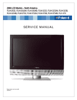
2006 LCD Models - North America FLM-2632, FLM-2632M, FLM-2634B, FLM-3232, FLM-3232M, FLM-323B, FLM-3234B, FLM-3732, FLM-3732M, FLM-373B, FLM-3734B, FLX-374 SERVICE MANUAL Bezel covers vary by model 20070411 - Polaroid FLM-2632 | Service Manual - Page 2
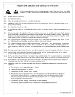
service manual, please ensure that you have carefully followed all the procedures outlined in the user's manual for this product. (1) Read all of these instructions. (2) Save these instructions. (3) Follow all warnings and instructions marked on the product. (4) Unplug this product from the wall - Polaroid FLM-2632 | Service Manual - Page 3
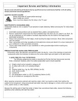
HAZARD Always disconnect AC power before servicing! Never modify any circuit! Never insert any objects into the holes in the TV case! ELECTROSTATIC DISCHARGE (ESD) Components inside an LCD or plasma TV are sensitive to static electricity. Before servicing the TV, follow these guidelines: • Avoid - Polaroid FLM-2632 | Service Manual - Page 4
not leave the bit powered on for extended periods. When the tip of the soldering bit is blackened during use, clean the bit with steel wool or fine sandpaper. (0) NOTICE ABOUT REPLACEMENT PARTS Many electrical and mechanical parts within LCD or plasma televisions are chosen for their specific safety - Polaroid FLM-2632 | Service Manual - Page 5
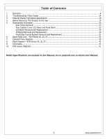
30 Front/Side Control Buttons Removal and Replacement 31 6. Spare Parts Lists - FLM-Series 26, 32, 37 32 7. Exploded View Diagram ...39 8. Block Diagram - FLM-Series 26, 32, 37 42 9. Schematics ...43 10. PCB Layout Diagrams ...51 Model Specifications are located in User Manual. Go to polaroid.com - Polaroid FLM-2632 | Service Manual - Page 6
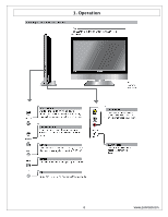
1. Operation 6 www.polaroid.com - Polaroid FLM-2632 | Service Manual - Page 7
7 www.polaroid.com - Polaroid FLM-2632 | Service Manual - Page 8
Original Remote Control 8 www.polaroid.com - Polaroid FLM-2632 | Service Manual - Page 9
9 www.polaroid.com - Polaroid FLM-2632 | Service Manual - Page 10
New Remote Control 10 www.polaroid.com - Polaroid FLM-2632 | Service Manual - Page 11
Factory Mode Procedure 1. Power on TV. 2. Press volume up and channel up buttons on the TV simultaneously and release. 3. Power off TV with remote or power button to exit. 11 www.polaroid.com - Polaroid FLM-2632 | Service Manual - Page 12
operation of each OSD control is described in the following table: Menu VIDEO AUDIO TV Options Picture Mode Contrast Brightness Saturation Hue Sharpness Color Temperature Bass Treble Balance Effect MTS Auto Search Tuner Mode Sub-Options Vivid →Hi-Bright →Cinema →Sport→User. 0...100 (75) 0...100 - Polaroid FLM-2632 | Service Manual - Page 13
HDTV Closed Caption V-chip Reset Audio Language Time Zone Auto Scan Manual Scan Channel Skip Analog Closed Caption Digital Closed Caption Digital Caption Style Block Channel C1,C2,C3,C4,T1,T2, Set the closed caption mode. TT4,and Off Input Password Block MPAA Rating Block TV Rating Block MPAA - Polaroid FLM-2632 | Service Manual - Page 14
2. Troubleshooting / Flow Charts Note: Reseat all cables, check fuse by AC plug, perform a clear or reset in factory mode and retest before ordering parts. Can't power on your TV? This TV is equipped with a safety fuse. In the event of an electrical storm or power outage the safety fuse is designed - Polaroid FLM-2632 | Service Manual - Page 15
15 www.polaroid.com - Polaroid FLM-2632 | Service Manual - Page 16
16 www.polaroid.com - Polaroid FLM-2632 | Service Manual - Page 17
17 www.polaroid.com - Polaroid FLM-2632 | Service Manual - Page 18
Cell Defect Specifications below define the allowed limits for display cell defects and are used as the criteria in determining whether an LCD panel is replaced. 7 or more defective pixels across the entire LCD screen Polaroid will repair (replace LCD panel) or replace the TV. 18 www.polaroid.com - Polaroid FLM-2632 | Service Manual - Page 19
ground. Measurement points include antenna, metal cabinet parts, screw heads, and metal knobs or controls. Measurement points can vary slightly even between revisions of the same model, so always conduct a thorough review of the chassis to locate metal points that a user may touch. d. Any voltage - Polaroid FLM-2632 | Service Manual - Page 20
any part the TV, make sure the power is OFF, and the power cord is removed from the wall outlet. Allow time for power within all system boards to discharge before you begin disassembly. Never insert any objects into the vent holes in the TV case. Note: Before returning this product to the end user - Polaroid FLM-2632 | Service Manual - Page 21
cloth between work bench and TV front. (2) Remove screws in the sequence indicated below (1 thru 6). (3) Remove stand. *NOTE: Pictured is a 26" model. 32" and 37" models will have different stand screw quantities and locations. Rear Cover Removal (4) Remove control box cover screws (PIC1 item - Polaroid FLM-2632 | Service Manual - Page 22
Aluminum foil covering the LVDS connector. Disconnect LVDS cable connector from LCD panel (PIC2). (9) Disconnect the LCD Panel power cord from bottom side of control box (PIC3). Note: Before returning this product to the end user, you must follow the steps outlined in the section, Before Returning - Polaroid FLM-2632 | Service Manual - Page 23
Rear Cabinet Cover LCD Panel and Front Bezel Note: Before disassembly of any part the TV, make sure the power is OFF, and the power cord is removed from the wall outlet. Allow time for power within all system boards to discharge before you begin disassembly. Never insert any objects into the vent - Polaroid FLM-2632 | Service Manual - Page 24
(5) Remove screws from TV stand support frame (PIC1) (6) Remove screws from TV stand support frame (PIC1). (7) Remove TV stand support frame. 24 www.polaroid.com - Polaroid FLM-2632 | Service Manual - Page 25
(8) Remove the EMI Aluminum Foil Sheilding Tape from the LCD Panel (PIC1, 2) (9) EMI Aluminum Foil Sheilding Tape must be replaced during assembly. Remove the EMI Aluminum Foil Shielding Tape which secures the Keyboard wiring to the panel. 25 www.polaroid.com - Polaroid FLM-2632 | Service Manual - Page 26
(10) Remove from the D-sub board Speaker wire, Front/Side Control Button wire, and A/V wire connectors (PIC1) (11) Remove the black tape from the Speaker wire and Ceramic ring (PIC2) (12) Replace black tape during assembly. 26 www.polaroid.com - Polaroid FLM-2632 | Service Manual - Page 27
and remove the A/V wire under the frame (PIC1). (14) Save foam spacer and place in position during assembly. (15) Remove the A/V subassembly from the bezel (PIC2). (16) Remove screws (PIC1) in the sequence: 1-2 (17) Disconnect the LCD Panel cable from the D-SUB board (PIC1) 27 www.polaroid.com - Polaroid FLM-2632 | Service Manual - Page 28
panel to the bezel (PIC1, PIC2) (19) TWO MEN REQUIRED!! Lift LCD Panel from the bezel (20) Replace LCD panel. (21) The front bezel can now be replaced if needed. Note: Before returning this product to the end user, you must follow the steps outlined in the section, Before Returning This Product to - Polaroid FLM-2632 | Service Manual - Page 29
disassembly of any part the TV, make sure the power is OFF, and the power cord is removed from the wall outlet. Allow time for power within all system boards to discharge before you begin disassembly. Never insert any objects into the vent holes in the TV case. (1) Disassemble control box cover and - Polaroid FLM-2632 | Service Manual - Page 30
of any part the TV, make sure the power is OFF, and the power cord is removed from the wall outlet. Allow time for power within all system boards to discharge before you begin disassembly. Never insert any objects into the vent holes in the TV case. (1) Disassemble rear control box cover and - Polaroid FLM-2632 | Service Manual - Page 31
disassembly of any part the TV, make sure the power is OFF, and the power cord is removed from the wall outlet. Allow time for power within all system boards to discharge before you begin disassembly. Never insert any objects into the vent holes in the TV case. (1) Disassemble control box cover and - Polaroid FLM-2632 | Service Manual - Page 32
26, 32, 37 Attention Service Centers Some models consist of parts with multiple versions. Replacement parts in the spare part lists with an asterisk (*) are multiple version parts. The TV serial number Model Version is used to identify the replacement part(s) needed for repair. Below is the Polaroid - Polaroid FLM-2632 | Service Manual - Page 33
Power Cord Audio Cable Composite Video Cable Component Cable Remote Control Control Box Assembly (CMO L01) Control Box Assembly (AUO V0) Control Box Assembly (QDI) Front/Side Control Button Bd. Front/Side Control Button Cover Silver IR Board Front/Side A/V Input Bd. 32" LCD Panel (CMO L01) 32" LCD - Polaroid FLM-2632 | Service Manual - Page 34
Black Rear Cabinet Control Box Cover Black Stand Assembly Silver Speaker (right or Left) LVDS Cable (AUO V0) LVDS Cable (AUO V1 V2) *Note - Model Version column - see "Attention Service Centers" info before ordering part. Polaroid FLM-2632 Part List Model Version Part Number Description 600 - Polaroid FLM-2632 | Service Manual - Page 35
Polaroid FLM-2634B Part List Part Number Description 600-181-3200-LIH AC Power Cord 621-181-60002H Audio Cable 621-181-2000H Composite Video Cable 621-181-3020P-1H Component Cable 845-B45-GF1XA-PH Remote Control 909-KS0-GF271XAH Control Box Assembly (CMO L01) 899-K00-GF271XAH Front - Polaroid FLM-2632 | Service Manual - Page 36
. Polaroid FLM-3232M Part List Part Number Description 600-181-3200-LIH AC Power Cord 621-181-60002H Audio Cable 621-181-2000H Composite Video Cable 621-181-3020P-1H Component Cable 845-C45-GF1XA-PH Remote Control 909-KS0-GF321XA Control Box Assembly (CMO L01) 899-K00-GF271XAH Front - Polaroid FLM-2632 | Service Manual - Page 37
Polaroid FLM-3234B Part List Model Version Part Number Description 600-181-3200-LIH AC Power Cord 621-181-60002H Audio Cable 621-181-2000H Composite Video Cable 621-181-3020P-1H Component Cable 845-C45-GF1XA-PH Remote Control 00, 01, 03 *909-KS0-GF321XA Control Box Assembly (CMO L01/ - Polaroid FLM-2632 | Service Manual - Page 38
FLM-3734B, FLX-374 Part List Part Number Description 600-181-3200-LIH AC Power Cord 621-181-60002H Audio Cable 621-181-2000H Composite Video Cable 621-181-3020P-1H Component Cable 845-C45-GF1XA-PH Remote Control 909-KS0-GF371XA Control Box Assembly (AUO V1) 899-K00-GF271XAH Front - Polaroid FLM-2632 | Service Manual - Page 39
Exploded View Diagram Model Numbers: FLM-2632, FLM-2632M, FLM-2634B 39 www.polaroid.com - Polaroid FLM-2632 | Service Manual - Page 40
Model Number: FLM-3232, FLM-323B, FLM-3232M, FLM-3234B 40 www.polaroid.com - Polaroid FLM-2632 | Service Manual - Page 41
Model Number: FLM-3732, FLM-373B, FLM-3732M, FLM-3734B, FLX-374 41 www.polaroid.com - Polaroid FLM-2632 | Service Manual - Page 42
polaroid.com 7. Block Diagram - FLM-Series 26, 32, 37 GF ATSC LCD TV MT8202E+MT5111+MT5351 BOARD 4 LAYERS HDMI HDMI DATA+/-[2...0] ATSC VI[23...0] HDTV Connector GPIO-3 NTSC TV AC TO DC Power NTSC Tuner Analog Tuner Board AC 110~240V Power +24V AD Board +24V Panel Power Module 4 2 - Polaroid FLM-2632 | Service Manual - Page 43
. Clock shield 12. Clock 13. CEC 14. NC 15. DDC CLK 16. DDC DATA 17. CEC/GND 18. +5V Power 19. Hot Plug Detect D-Sub Connector IN. (This function also can provides to HDTV.) D-Sub type Connector pin assignment 1. Red Video 2. Green Video 3. Blue Video 4. GND 5. Vdd from PC for DDC 6. Red - Polaroid FLM-2632 | Service Manual - Page 44
Sub 15 pin (female) x 1 Video (Composite) CVBS Signal NTSC, 4.43NTSC, PAL_M, PAL(B,G,H,D,N), SECAM 1.0Vp-p / 75Ω S-Video (Y/C) Signal Y, C Y: 1.0Vp-p / 75Ω 75Ω Pb/Cb, Pr/Cr: 0.7 ± 0.035Vp-p / 75Ω HDMI Timing RESOLUTION V FREQ Hz 720x480 60 H FREQ kHz 15.7 720x480 60 31.5 1920x1080 60 - Polaroid FLM-2632 | Service Manual - Page 45
VGA SVGA SVGA XGA XGA SXGA SXGA MAC Non-VESA STANDARD NTSC PAL(B,G,H,D,I) SECAM 4.43NTSC PAL-M PAL-N SDTV 525i SDTV 625i SDTV 480p HDTV 720p HDTV 1080i RGB PC Timing RESOLUTION V FREQ Hz 640x480 60 H FREQ kHz 31.47 640x480 75 14.50 12.65 12.65 14.50 27 27 27 74.2 74.2 45 www.polaroid.com - Polaroid FLM-2632 | Service Manual - Page 46
Power Source Sound Output AC100 - 240 V, 60/50 Hz 10W X2, 8 Ohm. Signal Connector Pin Assignment Pin Assignment 1. Red 2. Green 3. Blue 4. Ground 5. 12. SDA 8. Blue Ground 13. Horizontal Sync. 9. Not Connected 14. Vertical Sync. 10. Sync. Ground 15. SCL 46 www.polaroid.com - Polaroid FLM-2632 | Service Manual - Page 47
IR Board U1 V G O 3 2 1 IR-SENSOR VCC VCC VCC R1 100 R2 10K C1 0.1uF C2 10uF-0805 J1 City, Taipei County, Taiwan R.O.C. Tel: 886-2-2231-6789 Fax: 886-2-2232-4613 Title IR SENSOR PCB Size Document Number Rev A GF371-XU A Date: Tuesday , December 20, 2005 Sheet 1 of 1 47 www - Polaroid FLM-2632 | Service Manual - Page 48
Front/Side Control Buttons SW1 POWER-ON SW2 SOURCE SW3 MENU SW4 CH-UP SW5 CH-DOWN SW6 VOL-UP SW7 VOL-DOWN VCC R1 4.7K R2 4.7K R3 4.7K R4 4.7K R5 4.7K R6 4.7K R7 4.7K C1 0.1uF J1 VCC POWER 886-2-2232-4613 Title KEYPAD PCB Size Document Number Rev A GF371-XU A Date: Friday , September 30 - Polaroid FLM-2632 | Service Manual - Page 49
700MA 2 FRONT_A_L L5 RCA JACK Audio Input C5 R5 12pF 75 RClamp0504F AV AUX Board CON1 : FRONT AV INPUT/OUTPUT PCB 1 Proview Electronics (Taiwan) Co., LTD. 6F, NO.1, Pau-Sheng Rd., Yung-Ho City, Taipei County, Taiwan R.O.C. Tel: 886-2-2231-6789 Fax: 886-2-2232-4613 Title AUX AV PCB - Polaroid FLM-2632 | Service Manual - Page 50
polaroid.com 200PHD Series 2X8 (16pin) CON1 VCCSB 15 SW6-VOL-UP 13 SW4-CH-UP 11 SW2-SOURCE 9 LED_G 7 IR-OUT 5 LTDC_INT 3 LTDC_DATA 1 16 SW7-VOL-DOWN 14 SW5-CH-DOWN 12 SW3-MENU 10 SW1-POWER D-SUB 37 PIN Board 200PHD Series 2X4 ( 29 10 28 9 27 8 26 7 25 6 24 5 23 4 22 - Polaroid FLM-2632 | Service Manual - Page 51
9. PCB Layout Diagrams Front/Side Control Button Board (Component Side Top) Front/Side Control Button Board (Component Side Bottom) IR/LED Board (Component Side Top) AUX AV Board (Component Side Top) 51 www.polaroid.com - Polaroid FLM-2632 | Service Manual - Page 52
D-SUB 37 Pin Board (Component Side Top) D-SUB 37 Pin Board (Component Side Bottom) 52 www.polaroid.com
-
 1
1 -
 2
2 -
 3
3 -
 4
4 -
 5
5 -
 6
6 -
 7
7 -
8
-
9
-
10
-
11
-
12
-
13
-
14
-
15
-
16
-
17
-
18
-
19
-
20
-
21
-
22
-
23
-
24
-
25
-
26
-
27
-
28
-
29
-
30
-
31
-
32
-
33
-
34
-
35
-
36
-
37
-
38
-
39
-
40
-
41
-
42
-
43
-
44
-
45
-
46
-
47
-
48
-
49
-
50
-
51
-
52
 |
 |
2006 LCD Models – North America
FLM-2632, FLM-2632M, FLM-2634B, FLM-3232, FLM-3232M, FLM-323B,
FLM-3234B, FLM-3732, FLM-3732M, FLM-373B, FLM-3734B, FLX-374
SERVICE MANUAL
Bezel covers vary by model
20070411