Polaroid FLM-2634B Service Manual
Polaroid FLM-2634B - 26" LCD TV Manual
 |
UPC - 826219005472
View all Polaroid FLM-2634B manuals
Add to My Manuals
Save this manual to your list of manuals |
Polaroid FLM-2634B manual content summary:
- Polaroid FLM-2634B | Service Manual - Page 1
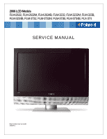
2006 LCD Models FLM-2632, FLM-2632M, FLM-2634B, FLM-3232, FLM-3232M, FLM-323B, FLM-3234B, FLM-3732, FLM-3732M, FLM-373B, FLM-3734B, FLX-374 SERVICE MANUAL Bezel covers vary by model 20070411 - Polaroid FLM-2634B | Service Manual - Page 2
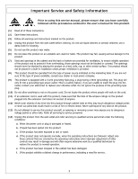
contact your electrician to replace your obsolete outlet. Do not ignore the purpose of the grounding-type plug. (10) Do not allow anything to rest on the power cord. Do not locate this product where people will walk on the cord. (11) If an extension cord is used with this product, make sure that the - Polaroid FLM-2634B | Service Manual - Page 3
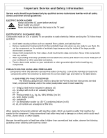
LCD or plasma TV are sensitive to static electricity. Before servicing the TV, follow these guidelines: • Avoid static-causing surfaces such as carpeted floors, plastic, and packing foam. • Remove replacement part of solder used in board assembly: e1 - time. When repairing components soldered with - Polaroid FLM-2634B | Service Manual - Page 4
or damaged. Do not leave the bit powered on for extended periods. When the tip of the soldering bit is blackened during use, clean the bit with steel wool or fine sandpaper. (0) NOTICE ABOUT REPLACEMENT PARTS Many electrical and mechanical parts within LCD or plasma televisions are chosen for their - Polaroid FLM-2634B | Service Manual - Page 5
LCD Panel and Front Bezel 23 A/V Board Removal and Replacement 29 IR Board Removal and Replacement 30 Front/Side Control Buttons Removal and Replacement 31 6. Spare Parts Lists - FLM-Series 26, 32, 37 32 7. Exploded View Diagram ...39 8. Block Diagram - FLM-Series 26, 32, 37 42 9. Schematics - Polaroid FLM-2634B | Service Manual - Page 6
1. Operation 6 - Polaroid FLM-2634B | Service Manual - Page 7
7 - Polaroid FLM-2634B | Service Manual - Page 8
Original Remote Control 8 - Polaroid FLM-2634B | Service Manual - Page 9
9 - Polaroid FLM-2634B | Service Manual - Page 10
New Remote Control 10 - Polaroid FLM-2634B | Service Manual - Page 11
Factory Mode Procedure 1. Power on TV. 2. Press volume up and channel up buttons on the TV simultaneously and release. 3. Power off TV with remote or power button to exit. 11 - Polaroid FLM-2634B | Service Manual - Page 12
. Red/Green/Blue: -19...+19 Fine tune the bass value. Fine tune the treble value. Fine tune the balance value. Select the preset effect mode to match your music type and achieve stunning effects. Close this function. Set the sound type, which is only available when input source is TV. Auto-search - Polaroid FLM-2634B | Service Manual - Page 13
Time Zone Auto Scan Manual Scan Channel Skip Analog Closed Caption Digital Closed Caption Digital Caption Style Block Channel C1,C2,C3,C4,T1,T2, Set the closed caption mode. TT4,and Off Input Password Block MPAA Rating Block TV Rating Block MPAA Unrated Block TV None Rating Reset to default value - Polaroid FLM-2634B | Service Manual - Page 14
your TV. If your TV has no power, check the fuse by prying the cover off, following the illustration below. If the fuse is blown, visit your local hardware store and ask for a 4A 250V - 5x20mm Time Lag Fuse (Slow Blow) to replace the fuse. Having trouble with setting your Parental Controls (V-Chip - Polaroid FLM-2634B | Service Manual - Page 15
15 - Polaroid FLM-2634B | Service Manual - Page 16
16 - Polaroid FLM-2634B | Service Manual - Page 17
17 - Polaroid FLM-2634B | Service Manual - Page 18
on The Polaroid Display Cell Defect Specifications below define the allowed limits for display cell defects and are used as the criteria in determining whether an LCD panel is replaced. 7 or more defective pixels across the entire LCD screen Polaroid will repair (replace LCD panel) or replace the TV - Polaroid FLM-2634B | Service Manual - Page 19
and a known earth ground. Measurement points include antenna, metal cabinet parts, screw heads, and metal knobs or controls. Measurement points can vary slightly even between revisions of the same model, so always conduct a thorough review of the chassis to locate metal points that a user may touch - Polaroid FLM-2634B | Service Manual - Page 20
Note: Before disassembly of any part the TV, make sure the power is OFF, and the power cord is removed from the wall outlet. Allow time for power within all system boards to discharge before you begin disassembly. Never insert any objects into the vent holes in the TV case. Note: Before returning - Polaroid FLM-2634B | Service Manual - Page 21
the front bezel and LCD screen from being scratched. Use protective cloth between work bench and TV front. Note: Before disassembly of any part the TV, make sure the power is OFF, and the power cord is removed from the wall outlet. Allow time for power within all system boards to discharge before - Polaroid FLM-2634B | Service Manual - Page 22
left (PIC3). (8) Tear off the Aluminum foil covering the LVDS connector. Disconnect LVDS cable connector from LCD panel (PIC2). (9) Disconnect the LCD Panel power cord from bottom side of control box (PIC3). Note: Before returning this product to the end user, you must follow the steps outlined in - Polaroid FLM-2634B | Service Manual - Page 23
part the TV, make sure the power is OFF, and the power cord is removed from the wall outlet. Allow time for power within all system boards to discharge before you begin disassembly. Never insert any objects into the vent holes in the TV case. Note: OEM LCD panels Pictured is a 26" model. 32" and 37" - Polaroid FLM-2634B | Service Manual - Page 24
(5) Remove screws from TV stand support frame (PIC1) (6) Remove screws from TV stand support frame (PIC1). (7) Remove TV stand support frame. 24 - Polaroid FLM-2634B | Service Manual - Page 25
(8) Remove the EMI Aluminum Foil Sheilding Tape from the LCD Panel (PIC1, 2) (9) EMI Aluminum Foil Sheilding Tape must be replaced during assembly. Remove the EMI Aluminum Foil Shielding Tape which secures the Keyboard wiring to the panel. 25 - Polaroid FLM-2634B | Service Manual - Page 26
(10) Remove from the D-sub board Speaker wire, Front/Side Control Button wire, and A/V wire connectors (PIC1) (11) Remove the black tape from the Speaker wire and Ceramic ring (PIC2) (12) Replace black tape during assembly. 26 - Polaroid FLM-2634B | Service Manual - Page 27
spacer from LCD Panel and remove the A/V wire under the frame (PIC1). (14) Save foam spacer and place in position during assembly. (15) Remove the A/V subassembly from the bezel (PIC2). (16) Remove screws (PIC1) in the sequence: 1-2 (17) Disconnect the LCD Panel cable from the D-SUB board (PIC1) 27 - Polaroid FLM-2634B | Service Manual - Page 28
to the bezel (PIC1, PIC2) (19) TWO MEN REQUIRED!! Lift LCD Panel from the bezel (20) Replace LCD panel. (21) The front bezel can now be replaced if needed. Note: Before returning this product to the end user, you must follow the steps outlined in the section, Before Returning This Product to - Polaroid FLM-2634B | Service Manual - Page 29
disassembly of any part the TV, make sure the power is OFF, and the power cord is removed from the wall outlet. Allow time for power within all system boards to discharge before you begin disassembly. Never insert any objects into the vent holes in the TV case. (1) Disassemble control box cover and - Polaroid FLM-2634B | Service Manual - Page 30
of any part the TV, make sure the power is OFF, and the power cord is removed from the wall outlet. Allow time for power within all system boards to discharge before you begin disassembly. Never insert any objects into the vent holes in the TV case. (1) Disassemble rear control box cover and - Polaroid FLM-2634B | Service Manual - Page 31
disassembly of any part the TV, make sure the power is OFF, and the power cord is removed from the wall outlet. Allow time for power within all system boards to discharge before you begin disassembly. Never insert any objects into the vent holes in the TV case. (1) Disassemble control box cover and - Polaroid FLM-2634B | Service Manual - Page 32
37 Attention Service Centers Some models consist of parts with multiple versions. Replacement parts in the spare part lists with an asterisk (*) are multiple version parts. The TV serial number Model Version is used to identify the replacement part(s) needed for repair. Below is the Polaroid serial - Polaroid FLM-2634B | Service Manual - Page 33
Power Cord Audio Cable Composite Video Cable Component Cable Remote Control Control Box Assembly (CMO L01) Control Box Assembly (AUO V0) Control Box Assembly (QDI) Front/Side Control Button Bd. Front/Side Control Button Cover Silver IR Board Front/Side A/V Input Bd. 32" LCD Panel (CMO L01) 32" LCD - Polaroid FLM-2634B | Service Manual - Page 34
AC Power Cord Audio Cable Composite Video Cable Component Cable Remote Control Control Box Assembly (AUO V1 V2) Control Box Assembly (AUO V0) Front/Side Control Button Bd. Front/Side Control Button Cover Silver IR Board Front/Side A/V Input Bd. 37" LCD Panel (AUO V2) 37" LCD Panel (AUO V1) 37" LCD - Polaroid FLM-2634B | Service Manual - Page 35
info before ordering part. Polaroid FLM-2634B Part List Part Number Description 600-181-3200-LIH AC Power Cord 621-181-60002H Audio Cable 621-181-2000H Composite Video Cable 621-181-3020P-1H Component Cable 845-B45-GF1XA-PH Remote Control 909-KS0-GF271XAH Control Box Assembly (CMO L01 - Polaroid FLM-2634B | Service Manual - Page 36
AC Power Cord Audio Cable Composite Video Cable Component Cable Remote Control Control Box Assembly (CMO L01) Control Box Assembly (AUO V5) Control Box Assembly (QDI) Front/Side Control Button Bd. Front/Side Control Button Cover Silver IR Board Front/Side A/V Input Bd. 32" LCD Panel (AUO V5) 32" LCD - Polaroid FLM-2634B | Service Manual - Page 37
part. Polaroid FLM-3732/3732M Part List Model Version Part Number Description 600-181-3200-LIH AC Power Cord 621-181-60002H Audio Cable 621-181-2000H Composite Video Cable 621-181-3020P-1H Component Cable 845-C45-GF1XA-PH Remote Control 00, 01, 02, 03 *909-KS0-GF371XA Control Box - Polaroid FLM-2634B | Service Manual - Page 38
-C45-GF1XA-PH Remote Control 909-KS0-GF371XA Control Box Assembly (AUO V1) 899-K00-GF271XAH Front/Side Control Button Bd. 154-500-GF321H Front/Side Control Button Cover Black 899-E00-GF271XAH IR Board 899-A00-GF271XAH Front/Side A/V Input Bd. 705-537-401AX1H 37" LCD Panel (AUO V1) 151 - Polaroid FLM-2634B | Service Manual - Page 39
Exploded View Diagram Model Numbers: FLM-2632, FLM-2632M, FLM-2634B 39 - Polaroid FLM-2634B | Service Manual - Page 40
Model Number: FLM-3232, FLM-323B, FLM-3232M, FLM-3234B 40 - Polaroid FLM-2634B | Service Manual - Page 41
Model Number: FLM-3732, FLM-373B, FLM-3732M, FLM-3734B, FLX-374 41 - Polaroid FLM-2634B | Service Manual - Page 42
+24V LCD PANEL (1366x768 ) Keypad & IR & LED VIDEO1 Composite VIDEO3 S-Video VIDEO4 YPbPr1 (HDTV1) COMPUTER VIDEO5 VIDEO6 YPbPr2 (HDTV2) VGA HDMI-DVI VIDEO2 Composite L U10 L U10 H PI5V330 H PI5V330 GPIO-3 I/O Connector GPIO-3 NTSC TV AC TO DC Power NTSC Tuner Analog Tuner Board - Polaroid FLM-2634B | Service Manual - Page 43
8. Schematics HMDI connector is DDC CLK 16. DDC DATA 17. CEC/GND 18. +5V Power 19. Hot Plug Detect D-Sub Connector IN. (This function also can provides to 1. Red Video 2. Green Video 3. Blue Video 4. GND 5. Vdd from PC for DDC 6. Red Ground 7. Green Ground 8. Blue Ground 9. +5V from PC 10. - Polaroid FLM-2634B | Service Manual - Page 44
Ohm (Differential),50 Ohm (Single ending) Single Link Fh = 31~80 kHz Fv = 56~76 Hz 135 MHz Compliant with Revision 1.0 HDMI x 1 Analog HD15 PC Signal (RGB) R, G, B Analog 0.7Vp-p / 75Ω Compliant with Revision 1.0 H/V separate 3V TTL level / 1kΩ Fh = 31~80 kHz Fv = 56~76 Hz 135 Mhz Mini D-Sub - Polaroid FLM-2634B | Service Manual - Page 45
-N SDTV 525i SDTV 625i SDTV 480p HDTV 720p HDTV 1080i RGB PC Timing RESOLUTION V FREQ Hz 640x480 60 H FREQ kHz 31.47 640x480 75 37.5 800x600 60 37.88 800x600 75 46.9 1024x768 60 48.36 1024x768 75 60.02 1280x1024 60 64 1280x1024 75 80 640x480 67 35 720x400 70 31 - Polaroid FLM-2634B | Service Manual - Page 46
Power Source Sound Output AC100 - 240 V, 60/50 Hz 10W X2, 8 Ohm. Signal Connector Pin Assignment Pin Assignment 1. Red 2. Green 3. Blue 4. Ground 5. Self Test Pin Assignment Pin Assignment 6. Red Ground 11. Ground 7. Green Gro und 12. SDA 8. Blue Ground 13. Horizontal Sync. - Polaroid FLM-2634B | Service Manual - Page 47
IR Board U1 V G O 3 2 1 IR-SENSOR VCC VCC VCC R1 100 R2 10K C1 0.1uF C2 10uF-0805 J1 VCC City, Taipei County, Taiwan R.O.C. Tel: 886-2-2231-6789 Fax: 886-2-2232-4613 Title IR SENSOR PCB Size Document Number Rev A GF371-XU A Date: Tuesday , December 20, 2005 Sheet 1 of 1 47 - Polaroid FLM-2634B | Service Manual - Page 48
Control Buttons SW1 POWER-ON SW2 SOURCE SW3 MENU SW4 CH-UP SW5 CH-DOWN SW6 VOL-UP SW7 VOL-DOWN VCC R1 4.7K R2 4.7K R3 4.7K R4 4.7K R5 4.7K R6 4.7K R7 4.7K C1 0.1uF J1 VCC POWER : 886-2-2232-4613 Title KEYPAD PCB Size Document Number Rev A GF371-XU A Date: Friday , September 30, 2005 - Polaroid FLM-2634B | Service Manual - Page 49
AV AUX Board 4 9 FRONT_S_CHROMA R1 75 S-Video Input J1 FB-40-0805-700MA L1 S_C 3 CY 9 10 7 8 5 6 3 4 1 2 FRONT_A_L_IN PHONE_A_L_O PHONE_A_D_O FRONT_S_LUMA 200PHD-14LT LINK TO AUX AV PCB 1 Proview Electronics (Taiwan) Co., LTD. 6F, NO.1, Pau-Sheng Rd., Yung-Ho City, Taipei County, - Polaroid FLM-2634B | Service Manual - Page 50
PHONE_A_R_O FRONT_A_R_IN FRONT_S_LUMA 200PHD-14LT AUX AV D-SUB 37 PIN Board 5 0 200PHD Series 2X4 (8pin) CON3 VBLON SPK_R_OUTPHONE_A_L_O PHONE_A_R_O FRONT_A_R_IN FRONT_S_LUMA SW7-VOL-DOWN SW5-CH-DOWN SW3-MENU SW1-POWER LED_O LTDC_ADDR LTDC_CLK VBLON AD J _I N V Proview Electronics (Taiwan) - Polaroid FLM-2634B | Service Manual - Page 51
9. PCB Layout Diagrams Front/Side Control Button Board (Component Side Top) Front/Side Control Button Board (Component Side Bottom) IR/LED Board (Component Side Top) AUX AV Board (Component Side Top) 51 - Polaroid FLM-2634B | Service Manual - Page 52
D-SUB 37 Pin Board (Component Side Top) D-SUB 37 Pin Board (Component Side Bottom) 52
-
 1
1 -
 2
2 -
 3
3 -
 4
4 -
 5
5 -
 6
6 -
 7
7 -
8
-
9
-
10
-
11
-
12
-
13
-
14
-
15
-
16
-
17
-
18
-
19
-
20
-
21
-
22
-
23
-
24
-
25
-
26
-
27
-
28
-
29
-
30
-
31
-
32
-
33
-
34
-
35
-
36
-
37
-
38
-
39
-
40
-
41
-
42
-
43
-
44
-
45
-
46
-
47
-
48
-
49
-
50
-
51
-
52
 |
 |

2006 LCD Models
FLM-2632, FLM-2632M, FLM-2634B, FLM-3232, FLM-3232M, FLM-323B,
FLM-3234B, FLM-3732, FLM-3732M, FLM-373B, FLM-3734B, FLX-374
SERVICE MANUAL
Bezel covers vary by model
20070411