Polaroid FLM4234BH Service Manual
Polaroid FLM4234BH Manual
 |
View all Polaroid FLM4234BH manuals
Add to My Manuals
Save this manual to your list of manuals |
Polaroid FLM4234BH manual content summary:
- Polaroid FLM4234BH | Service Manual - Page 1
2006 LCD Models - North America FLM-4034B, FLM-4232HM, FLM-4234BH SERVICE MANUAL Bezel covers vary by model 20070415 - Polaroid FLM4234BH | Service Manual - Page 2
and Safety Information Prior to using this service manual, please ensure that you have carefully followed all the procedures outlined in the user's manual for this product. (1) Read all of these instructions. (2) Save these instructions. (3) Follow all warnings and instructions marked on the product - Polaroid FLM4234BH | Service Manual - Page 3
HAZARD Always disconnect AC power before servicing! Never modify any circuit! Never insert any objects into the holes in the TV case! ELECTROSTATIC DISCHARGE (ESD) Components inside an LCD or plasma TV are sensitive to static electricity. Before servicing the TV, follow these guidelines: • Avoid - Polaroid FLM4234BH | Service Manual - Page 4
Service e9 symbols are unassigned at this time. When repairing components soldered with lead-free solder, ONLY use joint. Leaving the bit in contact with parts for an extended period may damage the components corroded or damaged. Do not leave the bit powered on for extended periods. When the tip of - Polaroid FLM4234BH | Service Manual - Page 5
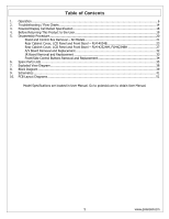
2. Troubleshooting / Flow Charts ...14 3. Polaroid Display Cell Defect Specification 18 4. Before Returning This Product to the User 19 5. Disassembly Procedure...20 Stand and Control Box Removal - All Models 21 Rear Cabinet Cover, LCD Panel and Front Bezel - FLM-4034B 23 Rear Cabinet Cover, LCD - Polaroid FLM4234BH | Service Manual - Page 6
1. Operation 6 www.polaroid.com - Polaroid FLM4234BH | Service Manual - Page 7
7 www.polaroid.com - Polaroid FLM4234BH | Service Manual - Page 8
Original Remote Control 8 www.polaroid.com - Polaroid FLM4234BH | Service Manual - Page 9
9 www.polaroid.com - Polaroid FLM4234BH | Service Manual - Page 10
New Remote Control 10 www.polaroid.com - Polaroid FLM4234BH | Service Manual - Page 11
11 www.polaroid.com - Polaroid FLM4234BH | Service Manual - Page 12
The operation of each OSD control is described in the following table: Menu VIDEO AUDIO TV Options Picture Mode Contrast Brightness Saturation Hue Sharpness Color Temperature Bass Treble Balance Effect MTS Auto Search Tuner Mode Sub-Options Vivid →Hi-Bright →Cinema →Sport→User. 0... - Polaroid FLM4234BH | Service Manual - Page 13
Manual Scan Channel Skip Analog Closed Caption Digital Closed Caption Digital Caption Style Block Channel C1,C2,C3,C4,T1,T2, Set the closed caption mode. TT4,and Off Input Password Block MPAA Rating Block TV Rating Block MPAA Unrated Block TV . To setup the block channel. 13 www.polaroid.com - Polaroid FLM4234BH | Service Manual - Page 14
Having trouble with setting Picture-in-Picture settings? The Picture-in-Picture will not work using Component 1 and Component 2 as the input sources. Factory Mode Procedure (1) Power on TV. (2) Press volume up and channel up buttons on the TV simultaneously and release. (3) Power off TV with remote - Polaroid FLM4234BH | Service Manual - Page 15
15 www.polaroid.com - Polaroid FLM4234BH | Service Manual - Page 16
16 www.polaroid.com - Polaroid FLM4234BH | Service Manual - Page 17
17 www.polaroid.com - Polaroid FLM4234BH | Service Manual - Page 18
Cell Defect Specifications below define the allowed limits for display cell defects and are used as the criteria in determining whether an LCD panel is replaced. 7 or more defective pixels across the entire LCD screen Polaroid will repair (replace LCD panel) or replace the TV. 18 www.polaroid.com - Polaroid FLM4234BH | Service Manual - Page 19
include antenna, metal cabinet parts, screw heads, and metal knobs or controls. Measurement points can vary slightly even between revisions of the same model, so always conduct a thorough review of the chassis to locate normal operation the product must use the proper polarity. 19 www.polaroid.com - Polaroid FLM4234BH | Service Manual - Page 20
part the TV, make sure the power is OFF, and the power cord is removed from the wall outlet. Allow time for power within all system boards to discharge before you begin disassembly. Never insert any objects into the vent holes in the TV . When servicing an LCD or plasma TV, always metal part of your - Polaroid FLM4234BH | Service Manual - Page 21
Stand and Control Box Removal - All Models Lay TV flat on workbench. Be careful to protect the front bezel and LCD screen from being scratched. Use protective cloth between work bench and TV front. Note: Before disassembly of any part the TV, make sure the power is OFF, and the power cord is removed - Polaroid FLM4234BH | Service Manual - Page 22
(3) Remove 2 screws (A) from the Control Box. A (4) Lift the Control Box upwards, and then towards to bottom of the TV to unhook it. (5) Unplug the 2 cables (A) from the Control Box, and remove the Box from the TV. A Note: Before returning this product to the end user, you must follow the steps - Polaroid FLM4234BH | Service Manual - Page 23
Rear Cabinet Cover, LCD Panel and Front Bezel - FLM-4034B Note: Before disassembly of any part the TV, make sure the power is OFF, and the power cord is removed from the wall outlet. Allow time for power within all system boards to discharge before you begin disassembly. Never insert any objects - Polaroid FLM4234BH | Service Manual - Page 24
and EMI Aluminum Foil Shielding Tape when reassembling the TV. (4) From the D-sub board, remove the Speaker wires, Front/Side Control Button wire, LCD Panel wire, and A/V wire. Speaker Wire Front/Side Control Button A/V Wire D-sub board LCD Panel Wire Black Tape (5) Remove the black tape - Polaroid FLM4234BH | Service Manual - Page 25
(6) Remove 8 screws (A) and remove the stand support frame from the TV. A (7) Remove 4 screws (A) from the left side frame support. A (8) Remove 4 screws (A) from the right side frame support. A 25 www.polaroid.com - Polaroid FLM4234BH | Service Manual - Page 26
4 screws (A) from the bottom of the left and right side frame supports, and remove the frame supports from the TV. A (10) Remove 6 screws (A) from the LCD Panel, and remove it from the TV. A NOTE: To avoid damage, TWO PEOPLE ARE REQUIRED to lift the LCD Panel from the TV. Note: Before returning this - Polaroid FLM4234BH | Service Manual - Page 27
Rear Cabinet Cover, LCD Panel and Front Bezel - FLM-4232HM, FLM4234BH Note: Before disassembly of any part the TV, make sure the power is OFF, and the power cord is removed from the wall outlet. Allow time for power within all system boards to discharge before you begin disassembly. Never insert any - Polaroid FLM4234BH | Service Manual - Page 28
and EMI Aluminum Foil Shielding Tape when reassembling the TV. (4) From the D-sub board, remove the Speaker wires, Front/Side Control Button wire, LCD Panel wire, and A/V wire. Speaker Wire Front/Side Control Button A/V Wire D-sub board LCD Panel Wire Black Tape (5) Remove the black tape - Polaroid FLM4234BH | Service Manual - Page 29
(6) Remove 12 screws (A) and remove the stand support frame from the TV. A (7) Remove 6 screws (A) from the left side frame support. A (8) Remove 6 screws (A) from the right side frame support. A 29 www.polaroid.com - Polaroid FLM4234BH | Service Manual - Page 30
right side frame support. Close-up of screws in frame support (2 screws in each slot). Close-up of screws in frame A support (2 screws in each slot). (11) Remove 2 screws (A) from the left and right frame supports (4 total), and remove both frame supports from the TV. A 30 www.polaroid.com - Polaroid FLM4234BH | Service Manual - Page 31
ARE REQUIRED to lift the LCD Panel from the TV. Note: Before returning this product to the end user, you must follow the steps outlined in the section, Before Returning This Product to the User, on page 19. This procedure ensures that the chassis will not cause electric shock. 31 www.polaroid.com - Polaroid FLM4234BH | Service Manual - Page 32
part the TV, make sure the power is OFF, and the power cord is removed from the wall outlet. Allow time for power within all system boards to discharge before you begin disassembly. Never insert any objects into the vent holes in the TV case. (1) Disassemble control box shock. 32 www.polaroid.com - Polaroid FLM4234BH | Service Manual - Page 33
part the TV, make sure the power is OFF, and the power cord is removed from the wall outlet. Allow time for power within all system boards to discharge before you begin disassembly. Never insert any objects into the vent holes in the TV case. (1) Disassemble rear control box . 33 www.polaroid.com - Polaroid FLM4234BH | Service Manual - Page 34
part the TV, make sure the power is OFF, and the power cord is removed from the wall outlet. Allow time for power within all system boards to discharge before you begin disassembly. Never insert any objects into the vent holes in the TV case. (1) Disassemble control box shock. 34 www.polaroid.com - Polaroid FLM4234BH | Service Manual - Page 35
to identify the correct replacement part(s) before placing replacement part orders. In the event the TV Model Version is not present in the part lists please review service bulletins for this model. Service bulletins can be obtained through your Polaroid service contact. C Month of Production Year - Polaroid FLM4234BH | Service Manual - Page 36
LVDS Cable (Samsung) Polaroid FLM-4232HM Part Number Description 600-181-3200-LIH AC Power Cord 621-181-60002H Audio Cable 621-181-2000H Composite Video Cable 621-181-3020P-1H Component Cable 845-C45-GF1XA-PEH Remote Control 909-KJ1-GF421UA2H Control Box Assembly (CMO L05) 899 - Polaroid FLM4234BH | Service Manual - Page 37
* 01 02 01 02 01 02 01 02 Polaroid FLM-4234BH Part Number Description 600-181-3200-LIH AC Power Cord 621-181-60002H Audio Cable 621-181-2000H Composite Video Cable 621-181-3020P-1H Component Cable 845-C45-GF1XA-PH Remote Control 909-KJ0-GF421UA2H Control Box Assembly (CMO L05) 909-KL0 - Polaroid FLM4234BH | Service Manual - Page 38
FLM-4034B 7. Exploded View Diagram FLM-4232HM, FLM-4234BH 38 www.polaroid.com - Polaroid FLM4234BH | Service Manual - Page 39
8. Block Diagram 39 www.polaroid.com - Polaroid FLM4234BH | Service Manual - Page 40
40 www.polaroid.com - Polaroid FLM4234BH | Service Manual - Page 41
Power & LDO 9. Schematics 41 www.polaroid.com - Polaroid FLM4234BH | Service Manual - Page 42
VGA In / LVDS & Back Light 42 www.polaroid.com - Polaroid FLM4234BH | Service Manual - Page 43
Audio ADC/DAC & OP 43 www.polaroid.com - Polaroid FLM4234BH | Service Manual - Page 44
GPIO & Placement 44 www.polaroid.com - Polaroid FLM4234BH | Service Manual - Page 45
Power 45 www.polaroid.com - Polaroid FLM4234BH | Service Manual - Page 46
Tuner 46 www.polaroid.com - Polaroid FLM4234BH | Service Manual - Page 47
Clock shield 12. Clock 13. CEC 14. NC 15. DDC CLK 16. DDC DATA 17. CEC/GND 18. +5V Power 19. Hot Plug Detect D-Sub Connector IN. (This function also can provides to HDTV.) D-Sub type Connector pin assignment pin assignment is described as below: 1: Ground 2: Ground 3: Y 4: C 47 www.polaroid.com - Polaroid FLM4234BH | Service Manual - Page 48
60 H FREQ kHz 15.7 720x480 60 31.5 1920x1080 60 33.7 1280x720 60 45.0 720x576 50 15.6 CLK MHz 27 27 74.2 74.2 27 48 www.polaroid.com - Polaroid FLM4234BH | Service Manual - Page 49
135 30.24 28 CLK MHz 12.65 14.50 14.50 12.65 12.65 14.50 27 27 27 74.2 74.2 49 www.polaroid.com - Polaroid FLM4234BH | Service Manual - Page 50
Power Source Sound Output AC100 - 240 V, 60/50 Hz 10W X2, 8 Ohm. Signal Connector Pin Assignment Pin Assignment 1. Red 2. Green 3. Blue 4. Gro und 12. SDA 8. Blue Ground 13. Horizontal Sync. 9. Not Connected 14. Vertical Sync. 10. Sync. Ground 15. SCL 50 www.polaroid.com - Polaroid FLM4234BH | Service Manual - Page 51
10. Keypad Board (Component Side Top) PCB Layout Diagrams Keypad Board (Component Side Bottom) IR/LED Board (Component Side Top) AUX AV Board (Component Side Top) 51 www.polaroid.com - Polaroid FLM4234BH | Service Manual - Page 52
D-SUB 37 Pin Board (Component Side Top) 52 www.polaroid.com
-
 1
1 -
 2
2 -
 3
3 -
 4
4 -
 5
5 -
 6
6 -
 7
7 -
8
-
9
-
10
-
11
-
12
-
13
-
14
-
15
-
16
-
17
-
18
-
19
-
20
-
21
-
22
-
23
-
24
-
25
-
26
-
27
-
28
-
29
-
30
-
31
-
32
-
33
-
34
-
35
-
36
-
37
-
38
-
39
-
40
-
41
-
42
-
43
-
44
-
45
-
46
-
47
-
48
-
49
-
50
-
51
-
52
 |
 |

2006 LCD Models – North America
FLM-4034B, FLM-4232HM, FLM-4234BH
SERVICE MANUAL
Bezel covers vary by model
20070415