Polaroid TLA-04641C Service Manual
Polaroid TLA-04641C - 46" LCD TV Manual
 |
View all Polaroid TLA-04641C manuals
Add to My Manuals
Save this manual to your list of manuals |
Polaroid TLA-04641C manual content summary:
- Polaroid TLA-04641C | Service Manual - Page 1
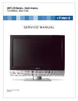
2007 LCD Models - North America TLA-04641C, 4641-TLXB SERVICE MANUAL Bezel covers vary by model 20070605 - Polaroid TLA-04641C | Service Manual - Page 2
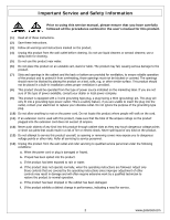
the product does not operate normally, when the operating instructions are followed. Adjust only those controls that are covered by the operating instructions since improper adjustment of other controls may result in damage and will often require extensive work by a qualified technician to restore - Polaroid TLA-04641C | Service Manual - Page 3
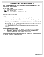
HAZARD Always disconnect AC power before servicing! Never modify any circuit! Never insert any objects into the holes in the TV case! ELECTROSTATIC DISCHARGE (ESD) Components inside an LCD or plasma TV are sensitive to static electricity. Before servicing the TV, follow these guidelines: • Avoid - Polaroid TLA-04641C | Service Manual - Page 4
solder comes in contact with a lead-free solder bit, subsequent solder joints will parts for an extended period may damage the components. (3) Because lead-free solder contains a higher concentration of tin, the tip of the soldering bit may be easily corroded or damaged. Do not leave the bit powered - Polaroid TLA-04641C | Service Manual - Page 5
3. Troubleshooting / Flow Charts...14 Factory Mode Procedure...14 4. Polaroid Display Cell Defect Specification 18 5. Before Returning This Product to the User 19 6. Disassembly Procedure ...20 Stand and Control Box Removal 21 Rear Cabinet Cover, LCD Panel and Front Bezel 23 IR Board Removal - Polaroid TLA-04641C | Service Manual - Page 6
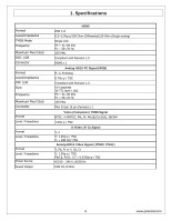
Maximum Pixel Clock Connector Format Level / Impedance Format Level / Impedance Format Level / Impedance Power Source Sound Output HDMI DVI 1.0 0.5~3.0Vp-p/100 Ohm (Differential),50 Ohm (Single ending) , Pr/Cr: 0.7 ± 0.035Vp-p / 75Ω AC100 - 240 V, 60/50 Hz 10W X2, 8 Ohm. 6 www.polaroid.com - Polaroid TLA-04641C | Service Manual - Page 7
Timing RESOLUTION V FREQ Hz 640x480 60 H FREQ kHz 31.47 640x480 75 37.5 800x600 60 37.88 800x600 75 46.9 1024x768 60 48.36 1024x768 75 60.02 1280x1024 60 64 1280x1024 75 80 640x480 67 35 720x400 70 31.5 27 27 74.2 74.2 CLK MHz 27 27 74.2 74.2 27 7 www.polaroid.com - Polaroid TLA-04641C | Service Manual - Page 8
2. Operation 8 www.polaroid.com - Polaroid TLA-04641C | Service Manual - Page 9
9 www.polaroid.com - Polaroid TLA-04641C | Service Manual - Page 10
Remote Control 10 www.polaroid.com - Polaroid TLA-04641C | Service Manual - Page 11
11 www.polaroid.com - Polaroid TLA-04641C | Service Manual - Page 12
of the picture up and down in the window. CLOCK Controls the width of the picture based on the VGA mode. Phase Controls the signal phase. It can improve the focus clarity : English / Spanish / French. Speaker Allows the selection of turning the TV speakers on or off. 12 www.polaroid.com - Polaroid TLA-04641C | Service Manual - Page 13
TV to SKIP, when scanning up/down channels the selected channel will be skipped. Set time zone. Set language. Select one Service 3 / Service4 / Service5 / Service6 / OFF Customize the settings for the digital closed caption option selected. Enter a 4-digit pin code. The default pin code polaroid.com - Polaroid TLA-04641C | Service Manual - Page 14
3. Troubleshooting / Flow Charts Note: Reseat all cables, check fuse by AC plug, perform a clear or reset in factory mode and retest before ordering parts. Can't power on your TV? This TV is equipped with a safety fuse. In the event of an electrical storm or power outage the safety fuse is - Polaroid TLA-04641C | Service Manual - Page 15
15 www.polaroid.com - Polaroid TLA-04641C | Service Manual - Page 16
16 www.polaroid.com - Polaroid TLA-04641C | Service Manual - Page 17
17 www.polaroid.com - Polaroid TLA-04641C | Service Manual - Page 18
Cell Defect Specifications below define the allowed limits for display cell defects and are used as the criteria in determining whether an LCD panel is replaced. 7 or more defective pixels across the entire LCD screen Polaroid will repair (replace LCD panel) or replace the TV. 18 www.polaroid.com - Polaroid TLA-04641C | Service Manual - Page 19
a 1.5k ohm, 10 watt resistor paralleled by a 0.15 µF capacitor. c. Using an AC voltmeter (sensitivity of 5000 ohm per volt or parts, screw heads, and metal knobs or controls. Measurement points can vary slightly even between revisions of the same model, so always conduct a thorough review polaroid.com - Polaroid TLA-04641C | Service Manual - Page 20
the section, Before Returning This Product to the User, on page 19. This procedure ensures that the chassis will not cause electric shock. When servicing an LCD or plasma TV, always observe the following safety guidelines: • Wear a grounding (ESD) wrist strap, and use a grounded or dissipative work - Polaroid TLA-04641C | Service Manual - Page 21
Stand and Control Box Removal Lay TV flat on workbench. Be careful to protect the front bezel and LCD screen from being scratched. Use protective cloth between work bench and TV front. Note: Before disassembly of any part the TV, make sure the power is OFF, and the power cord is removed from the - Polaroid TLA-04641C | Service Manual - Page 22
the Control Box, and remove the Box from the TV. A Note: Before returning this product to the end user, you must follow the steps outlined in the section, Before Returning This Product to the User, on page 19. This procedure ensures that the chassis will not cause electric shock. 22 www.polaroid - Polaroid TLA-04641C | Service Manual - Page 23
time for power within all system boards to discharge before you begin disassembly. Never insert any objects into the vent holes in the TV case. Note: OEM LCD panels were used in production. The following LCD panel disassembly/removal instructions may not apply to all models. Ensure LCD panel is - Polaroid TLA-04641C | Service Manual - Page 24
(2) Remove 6 screws (A) from between the bezel and rear cabinet cover, and remove the rear cabinet cover from the TV. A (3) Remove 9 screws (A) from the stand bracket and remove the stand bracket. A 24 www.polaroid.com - Polaroid TLA-04641C | Service Manual - Page 25
(4) Remove the aluminum foil (A) from the panel and SAVE for reassembly. Remove the brackets (B). A B (5) Remove 2 screws (A). Disconnect the D-Sub Board (B). A B (6) Remove 4 screws (A) from the side bracket. A 25 www.polaroid.com - Polaroid TLA-04641C | Service Manual - Page 26
(7) Remove 4 screws (A) from between the bracket and front bezel. A (8) Remove 4 screws (A) from one end of the support brackets. A (9) Remove 4 screws (A) from the other end of the support brackets. A 26 www.polaroid.com - Polaroid TLA-04641C | Service Manual - Page 27
ARE REQUIRED to lift the LCD Panel from the TV. Note: Before returning this product to the end user, you must follow the steps outlined in the section, Before Returning This Product to the User, on page 19. This procedure ensures that the chassis will not cause electric shock. 27 www.polaroid.com - Polaroid TLA-04641C | Service Manual - Page 28
disassembly of any part the TV, make sure the power is OFF, and the power cord is removed from the wall outlet. Allow time for power within all system boards to discharge before you begin disassembly. Never insert any objects into the vent holes in the TV case. (1) Disassemble control box cover and - Polaroid TLA-04641C | Service Manual - Page 29
disassembly of any part the TV, make sure the power is OFF, and the power cord is removed from the wall outlet. Allow time for power within all system boards to discharge before you begin disassembly. Never insert any objects into the vent holes in the TV case. (1) Disassemble control box cover and - Polaroid TLA-04641C | Service Manual - Page 30
SILV AC POWER CORD VIDEO CABLE COMPONENT CABLE LVDS CABLE (SAMSUNG L03) 46 LCD PANEL (SAMSUNG L03) SPEAKER R-L 26-46 UNIVERSAL REMOTE SILV/BLK 26-46 FRONT/SIDE AV INPUT BD 26-46 IR BOARD ASSY 26-46 FRNT/SIDE CONTROL BTN BD 46 CNTRL BOX ASSY (SAMSUNG L03) Polaroid Model 4641-TLXB Part Number 125 - Polaroid TLA-04641C | Service Manual - Page 31
8. Exploded View Diagram 31 www.polaroid.com - Polaroid TLA-04641C | Service Manual - Page 32
9. Block Diagram 32 www.polaroid.com - Polaroid TLA-04641C | Service Manual - Page 33
Power 10. Schematics 33 www.polaroid.com - Polaroid TLA-04641C | Service Manual - Page 34
VGA Input 34 www.polaroid.com - Polaroid TLA-04641C | Service Manual - Page 35
YPBR Input 35 www.polaroid.com - Polaroid TLA-04641C | Service Manual - Page 36
HDMI Input 36 www.polaroid.com - Polaroid TLA-04641C | Service Manual - Page 37
AV / SV Input 37 www.polaroid.com - Polaroid TLA-04641C | Service Manual - Page 38
Tuner Input 38 www.polaroid.com - Polaroid TLA-04641C | Service Manual - Page 39
IR Sensor/LED Board 39 www.polaroid.com - Polaroid TLA-04641C | Service Manual - Page 40
Clock shield 12. Clock 13. CEC 14. NC 15. DDC CLK 16. DDC DATA 17. CEC/GND 18. +5V Power 19. Hot Plug Detect D-Sub Connector IN. (This function also can provides to HDTV.) D-Sub type Connector pin assignment assignment is described as below: 1: Ground 2: Ground 3: Y 4: C 40 www.polaroid.com - Polaroid TLA-04641C | Service Manual - Page 41
6. Red Ground 11. Ground 7. Green Ground 12. SDA 8. Blue Ground 13. Horizontal Sync. 9. Not Connected 14. Vertical Sync. 10. Sync. Ground 15. SCL 41 www.polaroid.com - Polaroid TLA-04641C | Service Manual - Page 42
11. Keypad Board (Component Side Top) PCB Layout Diagrams Keypad Board (Component Side Bottom) IR/LED Board (Component Side Top) AUX AV Board (Component Side Top) 42 www.polaroid.com - Polaroid TLA-04641C | Service Manual - Page 43
D-SUB 37 Pin Board (Component Side Top) 43 www.polaroid.com
-
 1
1 -
 2
2 -
 3
3 -
 4
4 -
 5
5 -
 6
6 -
 7
7 -
8
-
9
-
10
-
11
-
12
-
13
-
14
-
15
-
16
-
17
-
18
-
19
-
20
-
21
-
22
-
23
-
24
-
25
-
26
-
27
-
28
-
29
-
30
-
31
-
32
-
33
-
34
-
35
-
36
-
37
-
38
-
39
-
40
-
41
-
42
-
43
 |
 |
2007 LCD Models – North America
TLA-04641C, 4641-TLXB
SERVICE MANUAL
Bezel covers vary by model
20070605