Poulan 380ZX Parts List
Poulan 380ZX Manual
 |
View all Poulan 380ZX manuals
Add to My Manuals
Save this manual to your list of manuals |
Poulan 380ZX manual content summary:
- Poulan 380ZX | Parts List - Page 1
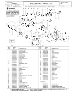
36 37 38 49 50 40 12 42 43 19 47 Chain Saw Model(s): 380 PAGE NO. 1 33 34 41 17 39 44 16 45 Muffler Diffuser Screw Operator Manual Warning Decal Kickback Warning Decal Bar&Chain Replacement Decal n = NEW PART NUMBER FOR THIS IPL K = REFER TO THE SERVICE REFERENCE INDICATED FOR MORE - Poulan 380ZX | Parts List - Page 2
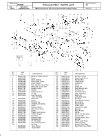
3/29/05 REPLACES 530085495-- 8/30/00 WPPOEAUERPLDAOAMUENOLAPATURNENRROTRRrRPPPAAPARRARTRTTSSTSSLLLIILSSISITTSTT Note: Illustration may differ from actual model due to design changes Chain Saw Model(s): 380 PAGE NO. 2 20 2 14 1 2 48 5 23 Gasket Kit 13 KEY NO. PART NO. 1 530027732 - Poulan 380ZX | Parts List - Page 3
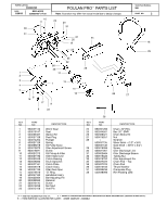
3/4") Screw Oiler Discharge Line Oiler Discharge Sleeve Tubing Nut Oiler Adjustment Pin Chain Pad -- Top Chain Pad Thrust Washer Crankcase Plug Rim Floating (3/8) n = NEW PART NUMBER FOR THIS IPL K = REFER TO THE SERVICE REFERENCE INDICATED FOR MORE INFORMATION. (LOCATED AT END OF IPL) D = THESE - Poulan 380ZX | Parts List - Page 4
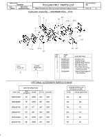
PARTS LIST NO. 530085495 DATE 3/29/05 REPLACES 530085495-- 8/30/00 WPPOEAUERPLDAOAMUENOLAPATURNENRROTRRrRPPPAAPARRARTRTTSSTSSLLLIILSSISITTSTT Note: Illustration may differ from actual model due to design changes Carburetor Assembly -- 530069895 HDA -- #137 3 12 3 KIT KIT KIT D KIT D Chain
-
 1
1 -
 2
2 -
 3
3 -
 4
4
 |
 |
r
POULAN PRO
PARTS LIST
1
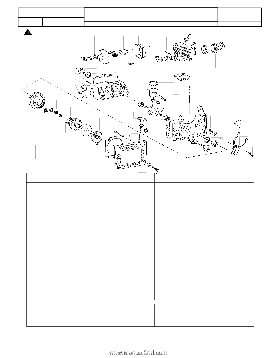
Note:
Illustration may differ from actual model due to design changes
PARTS LIST NO.
PAGE
NO.
Chain Saw Model(s):
380
DATE
8/30/00
530085495
REPLACES
530085495--1/14/99
Flywheel Ass’y.
Nut--Flywheel
Spring--Starter Dog
Washer
Starter Pulley
Starter Spring
Baffle Plate
Fan Housing Ass’y.
Screw
Washer
Screw
Muffler Back Plate
T1
T2
Eyelet Replacement Kit
Screw
Starter Handle
Boot
Screw
Rope Kit
Clip
Oil Cap Ass’y. (Incl. “O” Ring)
Screw
Ignition Module
Screw
Screw
Clamp
Crankshaft Bearing
Flywheel Key
Connecting Rod Ass’y.
Piston Pin Bearing
Piston Kit (Incl. 29, 46 & 50)
KEY
NO.
PART
NO.
DESCRIPTION
1
2
3
4
5
6
7
8
9
10
11
12
13
14
15
16
17
18
19
20
21
22
23
24
25
26
27
28
29
30
530069890
530049819
530023817
530016242
530052257
530042087
530052435
530052279
530015812
530015441
530015920
--
530049392
530053595
530069235
530015241
530049797
530030202
530015720
530069919
530015696
530010846
530015708
530039128
530015707
530015306
530027264
530032093
530002595
530027143
530032111
530069549
530015650
952027846
530019146
530069893
530016259
530015722
--
530069796
530053465
530030205
530069891
530021118
530001516
530069892
952030164
530027285
530036176
530015697
530001624
530015629
--
530049361
530053596
530049362
530016080
530088753
530047839
530047941
530052381
Screw
Spur
Crankshaft Seal
Crankcase Ass’y.
Screw
Washer
Muffler Cover
T1
T2
Spark Arrestor Screen
Gasket Kit
Muffler Gasket
Snap Ring
Cylinder Ass’y.
Spark Plug (RCJ--6Y)
Clamp Ass’y.
Piston Ring
Retainer
Screw
Washer
Muffler Body
T1
T2
Muffler Diffuser
Screw
Operator Manual
Warning Decal
Kickback Warning Decal
Bar&Chain Replacement Decal
31
32
33
34
35
36
37
38
39
40
41
42
43
44
45
46
47
48
49
50
51
KEY
NO.
PART
NO.
DESCRIPTION
Not Shown
1
2
3
4
5
6
8
7
9
10
15
28
11
34
17
27
29
45
46
30
23
31
32
33
41
39
38
37
36
35
12
40
43
19
47
16
44
20
26
21
22
24
25
34
14
18
13
All repairs, adjustments
and maintenance not de-
scribed in the Operator’s
Manual
must
be
per-
formed by qualified ser-
vice personnel.
WARNING
Gasket
Kit
39
42
33
41
48
49
50
51
51
=
REFER TO THE SERVICE REFERENCE INDICATED FOR MORE INFORMATION. (LOCATED AT END OF IPL)
D
K
=
THESE PARTS ARE ILLUSTRATED FOR CLARITY.
ORDER COMPLETE
ASSEMBLY.
=
NEW PART NUMBER FOR THIS IPL
n